71
9 Diagnosis, asset management and service
VEGAPULS 62 • Probus PA
36505-EN-181127
1
2
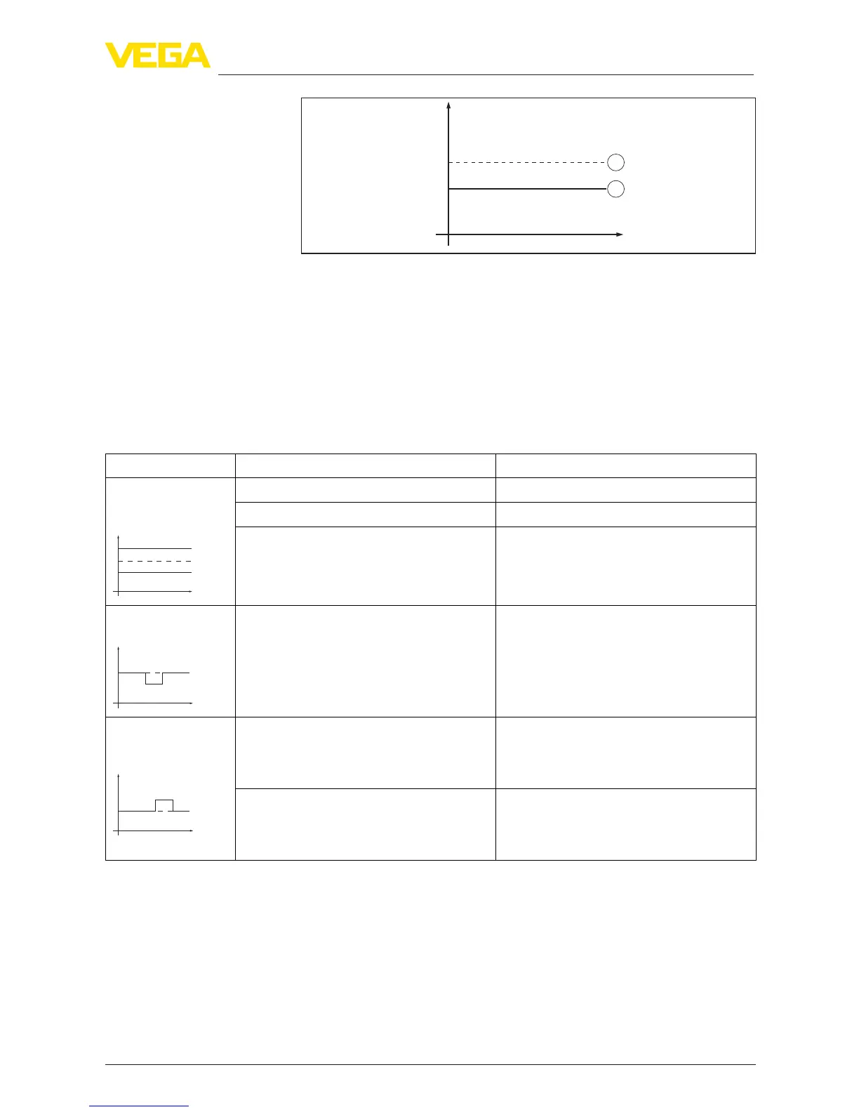
Level
time
0
1 Real level
2 Level displayed by the sensor
Notes:
•
Wherever the sensor displays a constant value, the reason could
also be the fault setting of the current output to "Hold value"
•
If the level indication is too low, the reason could be a line resist-
ance that is too high
Measurement error with constant level
Fault description Cause Rectication
1. Measured value
shows a too low or
too high level
Level
•
Min./max. adjustment not correct
•
Adapt min./max. adjustment
•
Incorrect linearisation curve
•
Adapt linearisation curve
•
Installation in a bypass tube or standpipe,
hence running time error (small measure-
ment error close to 100 %/large error
close to 0 %)
•
Check parameter "Application" with
respect to vessel form, adapt if necessary
(bypass, standpipe, diameter)
2. Measured value
jumps towards 0 %
Level
•
Multiple echo (vessel top, product
surface) with amplitude higher than the
level echo
•
Check parameter "Application", especially
vessel top, type of medium, dished bot-
tom, high dielectric constant, and adapt if
necessary
3. Measured val-
ue jumps towards
100 %
Level
•
Due to the process, the amplitude of the
level echo sinks
•
A false signal suppression was not carried
out
•
Carry out a false signal suppression
•
Amplitude or position of a false signal has
changed (e.g. condensation, buildup);
false signal suppression no longer
matches actual conditions
•
Determine the reason for the changed
false signals, carry out false signal sup-
pression, e.g. with condensation





 To Next Page