72
9 Diagnosis, asset management and service
VEGAPULS 62 • Probus PA
36505-EN-181127
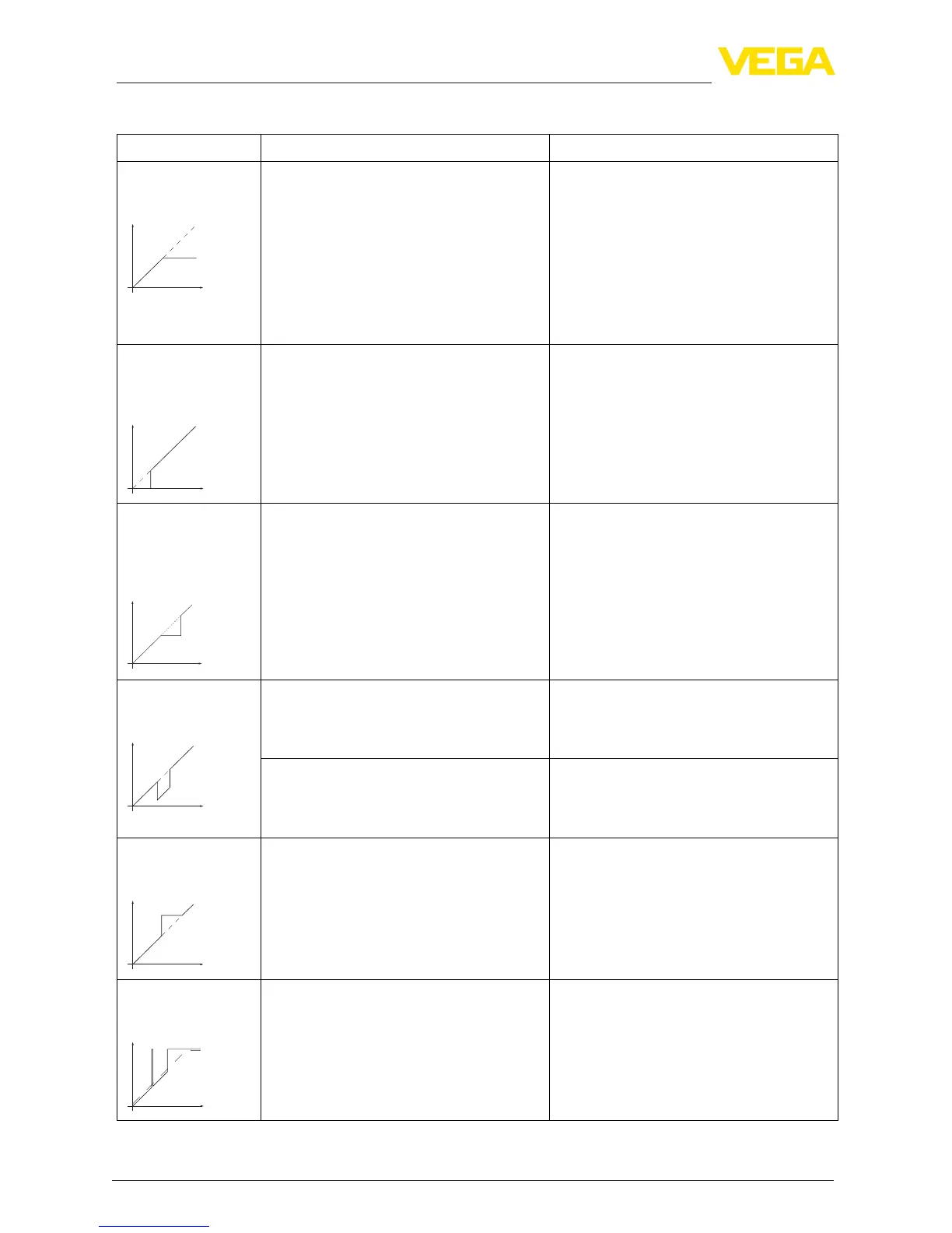
Measurementerrorduringlling
Fault description Cause Rectication
4. Measured value
remains unchanged
during lling
Level
•
False signals in the close range too big or
level echo too small
•
Strong foam or spout generation
•
Max. adjustment not correct
•
Eliminate false signals in the close range
•
Check measurement situation: Antenna
must protrude out of the socket, instal-
lations
•
Remove contamination on the antenna
•
In case of interferences due to installa-
tions in the close range: Change polarisa-
tion direction
•
Create a new false signal suppression
•
Adapt max. adjustment
5. Measured value
remains in the bot-
tom section during
lling
Level
•
Echo from the tank bottom larger than the
level echo, for example, with products with
ε
r
< 2.5 oil-based, solvents
•
Check parameters Medium, Vessel height
and Floor form, adapt if necessary
6. Measured value
remains momentar-
ily unchanged during
lling and then jumps
to the correct level
Level
•
Turbulence on the product surface, quick
lling
•
Check parameters, change if necessary,
e.g. in dosing vessel, reactor
7. Measured value
jumps towards 0 %
during lling
Level
•
Amplitude of a multiple echo (vessel top
- product surface) is larger than the level
echo
•
Check parameter "Application", especially
vessel top, type of medium, dished bot-
tom, high dielectric constant, and adapt if
necessary
•
The level echo cannot be distinguished
from the false signal at a false signal posi-
tion (jumps to multiple echo)
•
In case of interferences due to installa-
tions in the close range: Change polarisa-
tion direction
•
Chose a more suitable installation position
8. Measured val-
ue jumps towards
100 % during lling
Level
•
Due to strong turbulence and foam gen-
eration during lling, the amplitude of the
level echo sinks. Measured value jumps to
false signal
•
Carry out a false signal suppression
9. Measured value
jumps sporadically to
100 % during lling
Level
•
Varying condensation or contamination on
the antenna
•
Carry out a false signal suppression or
increase false signal suppression with
condensation/contamination in the close
range by editing





 To Next Page