44
PHTM II
Installation, Operating & Service Instructions
110331-01 - 5/20
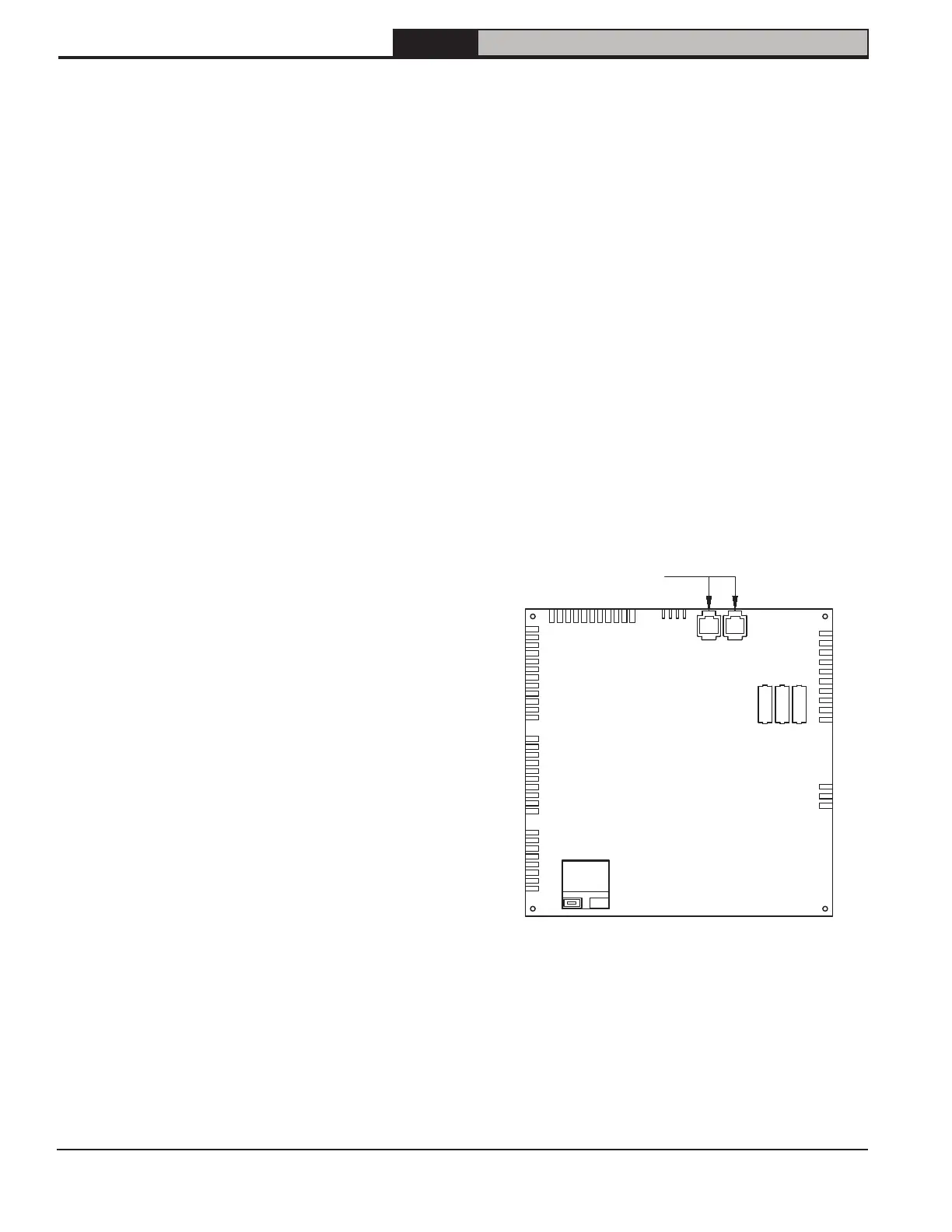
Figure 13-4: Boiler Peer-to-Peer Connections
X4
X5
X6
BCC
X2
Fuses
X1
X3
XB-2
XB-1
RJ45 Connections (2)
13 Field Wiring (continued)
2. External power must not be applied to any of low
voltage terminals - doing so may damage boiler
control. Note following:
A. External Limit: External limit terminals are
intended for use with field supplied safety
device, such as a manual reset high limit or
LWCO. When an external limit is used,
jumper between these two terminals must be
removed.
B. Outdoor Sensor - Use only Tasseron TSA00AA
(108681-01) outdoor sensor. When this sensor
is connected and enabled, boiler control
will provide outdoor air sensor based
freeze protection interlocks. When placing
sensor, consider following:
i. Locate sensor on outside of building.
ii. Avoid placing sensor in areas where it may
be covered with ice or snow.
iii. Avoid direct radiation from sun.
iv. Avoid placing sensor near potential
sources of electrical noise such as
transformers, power lines, and fluorescent
lighting.
v. Wire sensor to boiler using minimum 22
AWG wire.
vi. Where electrical noise sources cannot be
avoided, wire sensor using 2 conductor,
UL Type CM, AWM Style 2092 shielded
cable. Connect one end of shielding on
this cable to ground.
C. Header (recirculation) Sensor - When sensor
is installed and Comfort Mode is enabled,
boiler will attempt to maintain target domestic
hot water recirculation temperature in
recirculation piping. Use only Honeywell
32003971-003 (108709-01) sensor. Locate
sensor as shown in Figure 11-3. Wire sensor
using a 2 conductor, UL Type CM, AWM Style
2092, 300Volt 60°C shielded cable. Connect
one end of shielding on this cable to ground.
See Table 16-11 for information on enabling
recirculation sensor.
D. LWCO wiring - Although not necessary to
protect this boiler, some jurisdictions may
insist upon installation of LWCO with
this boiler.
• LWCO from these kits is installed to
4 pin connector on Low Voltage
Connections terminal strip. See
Section 10 Heating System Piping for
available LWCO kits compatible with this
boiler.
RJ45 Connections - Boiler-to-Boiler communication
network is used for multiple boiler ("Lead-Lag")
installations.
Note: Combi boilers may only be used as slaves in
such a system. Refer to Table 16-15 for information on
enabling this feature.
Boiler lead/lag sequencer connection is made directly
to control. Refer to Figure 13-4.