53110331-01 - 5/20
PHTM II
Installation, Operating & Service Instructions
16 Operation (continued)
Operating Mode
Basic boiler status is displayed and DHW setpoint
may be adjusted.
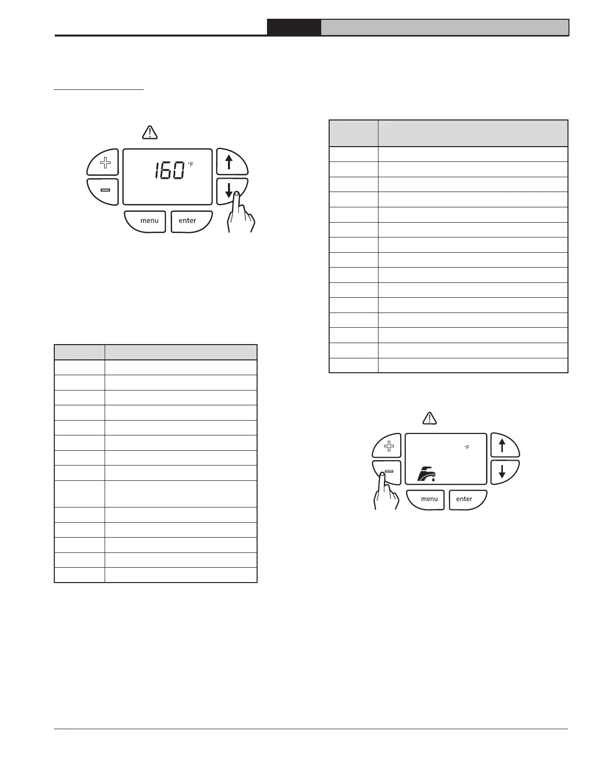
Figure 16-3:Viewing boiler status
Press "" or "" buttons to cycle through Status List.
Each item will alternate between status code and its
corresponding value.
Table 16-4: Status List
Display Description
StA
Status (see Table 16-5)
SP
Active, Operating Setpoint
bt
Boiler Supply Temperature
rt
Boiler Return Temperature
dt
DHW Temperature
dr
DHW Flow Rate
Ft
Flue Temperature
ot
Outdoor Air Temperature*
ht
Recirculation (header*)
Temperature
Fr
Firing Rate
rUn
Run Time Hours
CYC
Boiler Cycles
H##
Hold or Warning Condition
E##
Manual Reset Lockout
* Not available with local user display
The STA (status) display code contains below listed
values. This list is also available on display door label.
Table 16-5 Managing of Status Numbers
Display
Description (see Section 19
Troubleshooting for explanation)
0
Self Check
1
Standby
2
Waiting For Air Pressure Switch To Close
3
Prepurge
4
Burner Ignition
5
Calibration
6
Low Fire Hold
7
Rate Limit
8
Run (Modulate)
9
Postpurge
10
Pump air elimination (2 minutes)
11
Standby Delay
12
Lockout
13 Boiler On/Off Switch (A01)
14
Warm Weather Shutdown*
*
+
–
* Not available with local user display.
+
–
Figure 16-6: Adjusting DHW Setpoint
Press "+" or "-" buttons to immediately change the
DHW setpoint. Faucet and DHW Setpoint flash while
editing.
reset
reset