2 GR
Ignition
Electrode
X4
X5
26 RD
X6
BCC
7 BK
8 YE
11 BL
10 BR
9 BK
X2
Boiler Control
Board
T0.5A
T1.0A
T5.0A
T5.0A 250V Slow Blow, 5x20mm
T1.0A 250V Slow Blow, 5x20mm
T0.5A 250V Slow Blow, 5x20mm
Fuses
X1
6 RD
5 WH
4 WH
3 BK
2 GR
1 GR
34 OR
35 YE
33 Y/G
32 P/G
31 YE
30 P/G
29 PI
28 GY
27 GY
36 BL
25 R/G
X3
24 GY
23 BL
22 B/G
21 VI
20 V/G
19a PI
18a WH
17a BR
16 YE
15 Y/G
14 B/G
13 BL
40 OR/GY
10 GY
9 GY
39 PI
38 OR
8 BL
7 BK
6 WH
5 RD
4 Y/G
3 B/G
2 YE
1 BL
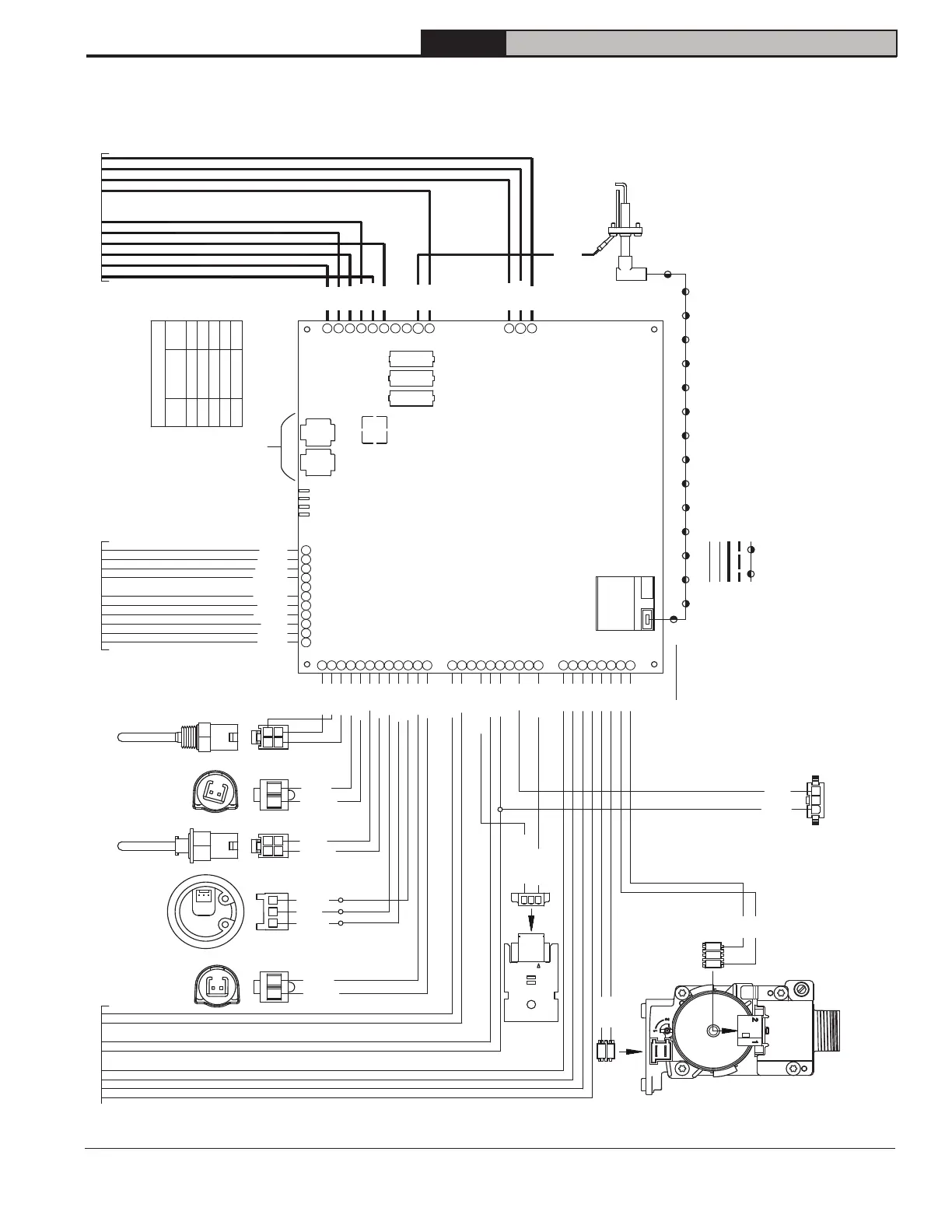
Line voltage field wiring
Ignitor - 250°C
Line voltage factory wiring size 18 AWG Type TEW/AWM stranded wire, 105°C
Low voltage factory wiring size 22 AWG Type TEW/AWM stranded wire, 105°C
Notes:
1. If any of the original wire supplied with the appliance must be replaced, it must be replaced with
the same type shown or its equivalent. S'IL faut remplacer un fil quelconque d'origine fourni avec.
2. Install over-current protection in accordance with Authority Having Jurisdiction or, in the absence of
such requirements, follow The National Electric Code, NFPA 70, and/or CSA C22.1 Electrical Code. Do not
provide over-current protection greater than 15 Amperes.
3. Plugs P1 & P2 are shown in line on PCB's for clarity.
1
1
2 YE
1 BL
CES10
Gas Valve
4 Y/G
3 B/G
Remote Monitor
Connector
1
3
1
3
Model
Key
Flue Temp.
Sensor
Supply
Sensor
2 1
4
3
3
1
2 1 2 1
2 1
4
3
Low voltage factory wiring size 20 AWG Type TEW/AWM stranded wire, 105°C
2
38 OR
40 OR/GY
3
2
39 PI
9a GY
23 BL
22 B/G
21 VI
20 V/G
16 YE
15 Y/G
Return
Sensor
DHW
Sensor
D4
P3
DHW Flow
Sensor
RJ45 RJ45
From Previous PageFrom Previous PageFrom Previous Page
X7
MB1
1
2
3
1
2
3
4
5
6
7
8
9
10
1
2
3
4
56
7
8910
11
1
2
3
4
5
6
7
8
9
10
11
12
1
2
3
4
5
6
7
8
9
10
1
2
3
4
5
6
7
8
X8-1X8-2
MB2 & MB3
Wire Color Code
BK - Black
BL - Blue
BR - Brown
GR - Green
GY - Gray
OR - Orange
PI - Pink
RD - Red
VI - Violet
WH - White
YE - Yellow
R/G - Red W/Gray tracer
B/G - Blue W/Gray tracer
P/G - Pink W/Gray tracer
V/G - Violet W/Gray tracer
Y/G - Yellow W/Gray tracer
OR/GY - Orange W/Gray tracer
OR/WH - Orange W/White tracer
GR/WH - Green W/White tracer
BR/WH - Brown W/White tracer
MB2 D+ (A)
MB2 GND (C)
MB2 D- (B)
MB3 D- (B)
MB3 D+ (A)
Connection
Wire
Color
OR/WH
OR
GR/WH
BR/WH
BR
PIN
1
2
3
7
8
X8-1, X8-2 Terminals
17 BR
19 PI
18 WH