Do you have a question about the Vemco VR60 and is the answer not in the manual?
Details the one-year warranty, its limitations, and excluded conditions.
Covers notice periods, remedy, and handling of returned items.
Includes license agreement, export compliance, and negotiated agreement terms.
Overview of VEMCO as a leader in oceanographic research tools since 1979.
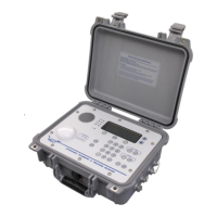
Description of the VR60 receiver's function and capabilities.
Details on the power switch, fuses, gain, volume, and signal level indicators.
Procedure for opening the case and description of data output port.
Method for selecting preselected operating frequencies.
Inspection steps and connecting the receiver and hydrophone.
Procedures for telemetry and tracking/locating applications.
Descriptions of Decoder/Display, Battery, Memory, Cable, Coded Transmitter, and Frequency options.
Keypad, display, serial port, and external control functionalities.
System alerts for declining power supply voltage.
Explanation of interactive prompts for decoded display operation.
Procedure for decoding data from specific transmitters.
Using Decode Period for pingers and measuring pulses per minute.
Setting and changing receiver frequencies.
Setting time, printer, log interval, and blanking interval.
Entering setup data, units, slope, and intercept for transmitters.
Examples and factors for converting depth and temperature units.
Charging procedures and expected battery life.
Estimating storage limits and calculating memory fill time.
Configuring the Log Interval for data storage.
Enabling/disabling data logging during decoding.
Visual indicators for memory usage and status.
Overview of viewing, printing, erasing, and dumping data.
Methods for downloading data to a computer and erasing memory.
Procedures for replacing batteries and post-replacement data erase.
Configuring for coded transmitters and identifying transmitter types.
Explains channels, sync/bin values for transmitter identification.
Table of alternative preset frequencies for the CHANNEL switch.
Software for receiver setup, data logging, and coded transmitters.
Option compatibility table and steps for software connection.
Definitions for key terms like Sync, Log Interval, and Blanking Interval.
Detailed technical specifications for the VR60 receiver unit.
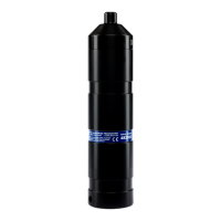
Technical specifications for VH65, V10, VH32, and V11 hydrophones.
Specific coded map details for the order (e.g., VEMCO Coded Map 'D').
List of available system diagrams, including schematics and layouts.
| Acoustic Frequency | 69 kHz |
|---|---|
| Maximum Depth | 500 m |
| Battery Life | Up to 10 years |
| Dimensions | 222 mm x 51 mm |
| Operating Depth | 500 m |
| Detection Range | 1000 m |