9
Decode
The Decode routine is used for decoding data telemetry transmitters # 1-12 whose calibration data
and frequency have been previously entered during the SETUP routine (see Setup section), or for
showing the raw time periods between incoming pulses. The period option is intended for
identifying simple pingers, or calibrating data telemetry units, and does not support printer outputs
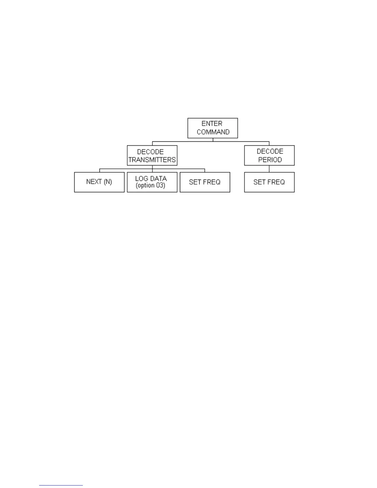
or data logging. The structure for the decode routine is shown below, with a detailed description of
each section to follow:
Decode Transmitters
Before data from a transmitter can be decoded, the calibration parameters must be stored in the
transmitter calibration data setup routine (see Transmitters Setup section). After the calibration data
has been entered, press the DECODE key on the keypad at the ENTER COMMAND prompt. The
display will read:
TR #? (1-12)
(0 for Period)
Enter the transmitter number (1-12) followed by ENTER. The display will show:
DECODING TR# n where n is the transmitter number entered.
If the Channel rotary switch is in the EXT position, the frequency associated with the transmitter
being decoded will appear in the second line. If the Channel switch is not in the EXT position, a
warning will appear on the display. This warning indicates that the desired frequency is being over-
ridden by the frequency set by the Channel switch. The switch must be at the EXT position for the
transmitter to be received and decoded. If a printer is being used, this warning is also printed to
avoid confusion during data analysis. Switching the channel rotary switch to EXT will select the
frequency corresponding to the decoded transmitter and will momentarily show the frequency on
the display.