2
HARDWARE
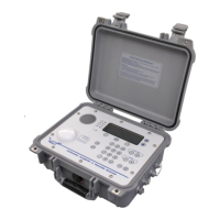
VR60 RECEIVER
Power Switch and Fuses
The power switch has four positions, OFF, ON, CHG (Charge) and AUX. The VR60 receiver is
powered with a 12-15 VDC power supply.
If the internal battery (Option 02) is installed in the VR60 receiver, the ON position will power the
receiver from the internal battery. The internal battery receives a float charge if an external power
supply is connected when the power switch is in the ON position (do not connect the external
power with the power switch in the ON position). To charge the internal battery with the receiver
not in operation, move the switch to the CHG (Charge) position as explained in the Internal Battery
(Option 02) section of this manual. The AUX position on the ON switch will power the VR60
receiver from an external power source without float charging the internal battery.
The main system fuse (1 A) is located on the receiver controller circuit board. A fuse (80 mA) for
an independent hydrophone is located on the VR60 receiver’s front panel (top left corner). If fitted
with an internal battery (Option 02), a fuse (1 A) is also located on the charge regulator board.
To Open the VR60 Case
To open the VR60 receiver case, six mounting screws on the front panel and two rubber feet must
be removed. The rubber feet that must be removed are on the same side of the VR60 case as the lid
closure clips, and are the two furthest from the clips. After the six mounting screws and two rubber
feet are removed, slowly pull the VR60 chassis from the case using the two handles. If the internal
battery has been installed (Option 02), be careful of the battery cable while removing the chassis.
Gain Control
The VR60 receiver gain may be controlled automatically by placing the front panel switch in the
AUTO position. When in automatic gain mode, the gain begins at the setting selected on the rotary
switch marked GAIN (dB) at the time the receiver was powered.
For tracking and locating applications, the gain may be manually controlled by placing the front
panel switch in the MANUAL position and using the rotary switch marked GAIN (dB) to set the
gain. The gain may be set in six decibel (6dB) increments, beginning at zero.