4. UNIT INSTALLATION (CONT’D)
13
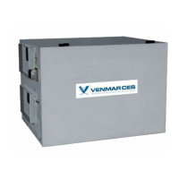
5.1 INTEGRATED CONTROL
Those units are equipped with an integrated control, located under the unit, on the recessed
side of electrical compartment. Plug the unit. Use the push button (1) to control the unit. The
LED (2) will then show on which mode the unit is in.
VD0207
1
2
Refer to table below to see how to operate the unit using its integrated control.
PRESS ON PUSH BUTTON LED COLOR RESULTS
ONCE AMBER UNIT IS ON LOW SPEED
TWICE GREEN UNIT IS ON HIGH SPEED
THREE TIMES NO LIGHT UNIT IS OFF
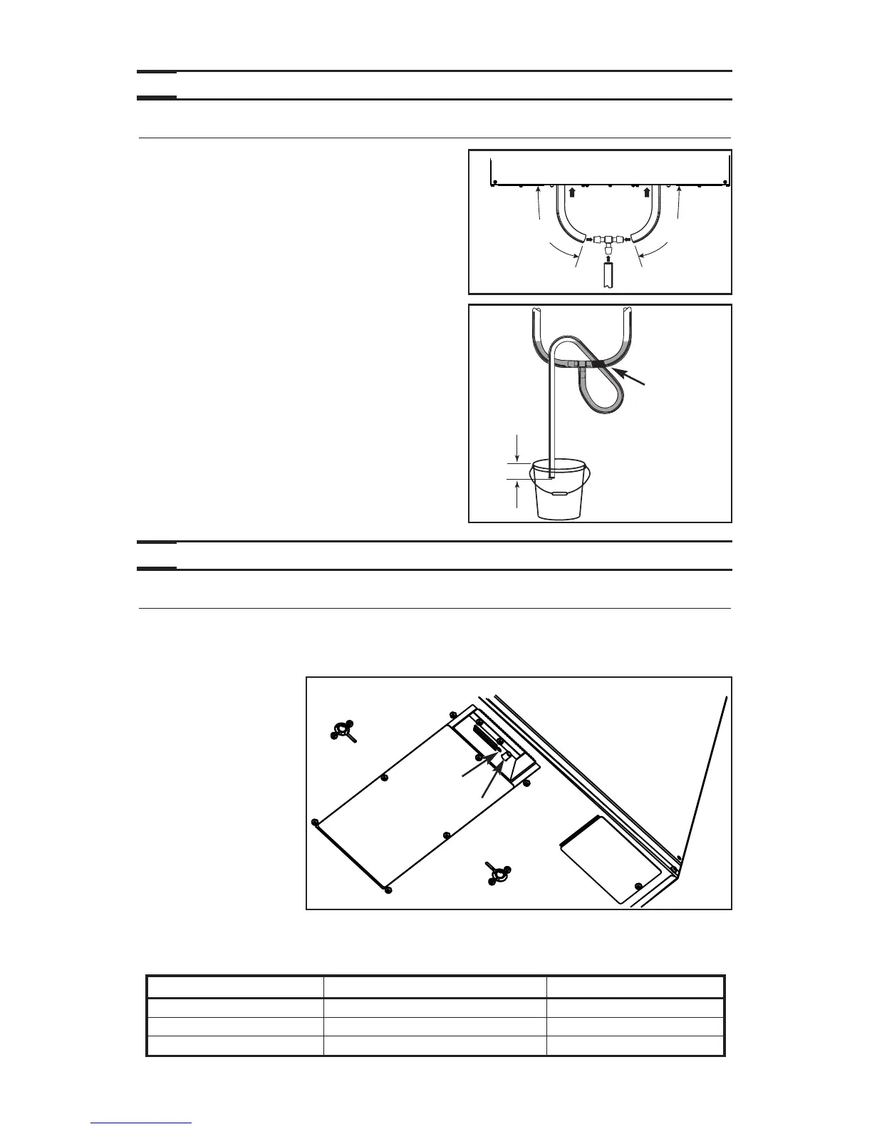
4.10 CONNECTING THE DRAIN
Make a water trap loop in the tube to prevent the
unit from drawing unpleasant odors from the drain
source. Make sure this loop is located OVER the
“T” as shown. Run the tube to the floor drain or to
an alternative drain pipe or pail.
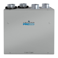
IMPORTANT
If using a pail to collect water, locate the tube end
approximately 1” from top of th epail in order to
prevent watter from being drawn back up into the
unit.
Cut 2 sections of the plastic tube, at least
16” (406 mm) long, and attach them to each inner
drain fitting, located under the unit. Join both
short sections to the “T” junction and main tube
as shown.
VO0154A
16"
(406 mm)
16"
(406 mm)
VD0232A
± 1”
TIE WRAP
5. CONTROLS
SEE PAGES 17 & 18
FORUNIT OPERAT ION.
BOTTOM OF THE UNIT