5. CONTROLS (CONT’D)
16
1. Route the cable from the unit to a convenient location for the control.
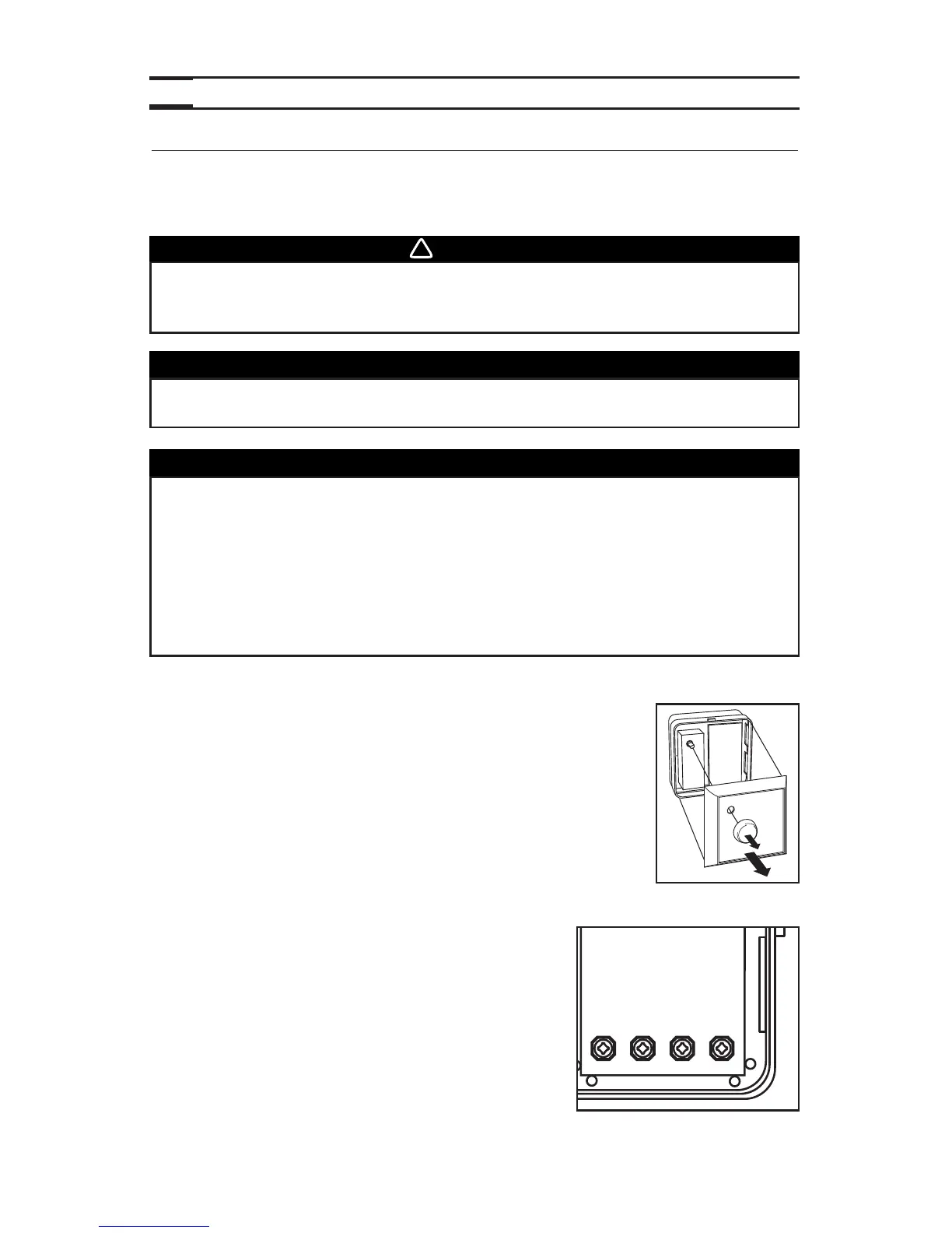
2. Remove the button and the cover plate of the control (see figure
beside). If necessary, bore the mounting holes and insert anchors.
3. Pass the cable (4 wires) through the opening of the mounting plate and mount the plate
to the wall using the provided screws.
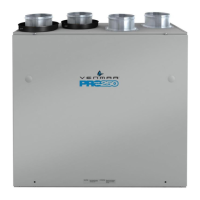
4. Splice back the end of the cable to access to the 4 wires.
Strip the end of each wire. Connect each wire to its
corresponding terminal: YELLOW wire to “Y’’, RED wire
to “R’’, GREEN to “G’’ and BLACK to “B’’. See illustration
beside.
5. Reinstall cover plate and button.
6. Plug the unit.
VC0110
5.3 MAIN CONTROLS INSTALLATION
For more convenience, the PRO250 and PRO225 units can also be controlled using the
included main controls: the Breeze main control for the PRO250 unit and the 11136 main
control for the PRO225 unit.
WARNING
Always disconnect the unit before making any connections. Failure in
disconnecting power could result in electrical shock or damage of the
control or electronic module inside the unit.
CAUTION
Failure to comply with the following can cause erratic operation of the unit:
• Never install more than one control per unit.
• Keep control low voltage wiring at least 1 foot (305 mm) away from
motors, lightning ballast, light dimming circuit and power distribution
panel. Do not route control wiring alongside electrical wires.
• Ensure the wires are securely connected.
• Disconnect power from the unit before removing the control faceplate
from its mounting plate.
The Breeze main control must be installed with the PRO250 unit only and
the 11136 main control with PRO225 unit.
CAUTION