3. DESCRIPTION OF THE UNIT
6
VL0035
16
14
8
11
9
3 214
10
9
11
8
13
12
6
5
7
12
15
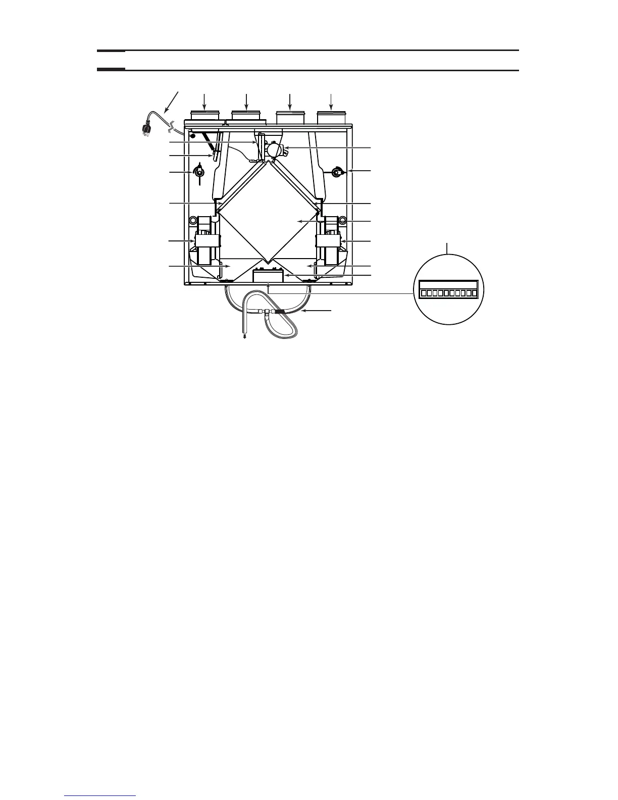
1 Exhaust port: exhausts stale air to the outside, after the air has transferred its
heat inside the heat recovery core.
2 Fresh air port: brings fresh air from the outside into the unit.
3 Stale air intake port: is connected to the registers located in the larger rooms of the
house.
4 Distribution port: distributes fresh air into the house, after it has absorbed the
heat of the stale air in the heat recovery core.
5 Main damper: allows fresh air intake when open and defrost when closed.
6 Secondary damper: allows stale air to exhaust when open and prevents negative
pressure when closed, in defrost mode.
7 Automatic defrost
unit :
consists of one damper actuator, dampers and related controls.
The defrost cycle is electronically controlled in response to the
outside temperature (-5°C [23°F] to -27°C [-17°F] or coldest)
and will increase in frequency as the temperature decreases.
Its duration is of 7 or 10 minutes.
8 Adjusting tools (2): adjust the dampers (one on each side) in balancing process.
Lock them in place once the unit is balanced.
9 Mechanical filters (2): trap the dust contained in the air and prevents the heat
recovery core from becoming obstructed.
10 Heat recovery core: is a crossflow type. It transf ers the heat between the two air
streams.
11 Blowers (2): dra w fresh air from the outside and exhaust stale air to the outside .
12 Condensation tray: is used to capture the water produced during heat transfer and
defrost (in cold climate).
13 Electrical cord: for 120 V electrical supply.
14 Electrical box: contains capacitors (indispensable to proper motors operation)
and electronic control circuit (insures proper operation of the
unit).
15 Terminal connector: located under the unit, allows to connect the controls.
16 Drainage tube: is connected to the condensation tray and serves to drain the
water accumulation.