VXR-9000 UHF Service Manual
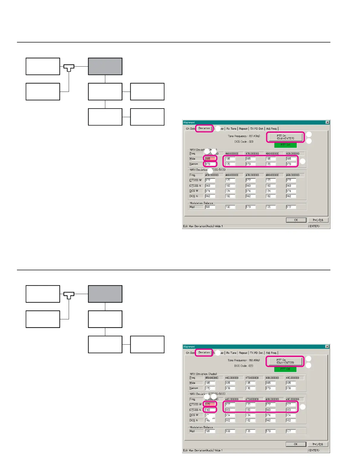
Sub-Audio (CTCSS) Deviation
Open the “Alignment” window, then click the left
mouse button on the “Deviation” tab to move to the
“Deviation” screen.
Click the left mouse button on the “CTCSS W” box on
the “Low Band Edge Frequency” area of the “MAX
Deviation (CTCSS/DCS)” field (highlighted in “pink”).
Click the left mouse button on the “PTT On” button to
actitvate the transmitter (the “PTT On” label is changed
to “PTT Off”).
Press the
[
Page Up
]
/
[
Page Down
]
key so that the De-
viation Meter reading is 0.75 kHz ±0.05 kHz.
Alignment
G-4
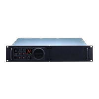
Maximum Deviation
Set the AF Signal Generator output to 35 mVrms at 1
kHz.
Open the “Alignment” window, then click the left
mouse button on the “Deviation” tab to move to the
“Deviation” screen.
Click the left mouse button on the “Wide” box on the
“Low Band Edge Frequency” area of the “MAX De-
viation (Audio)” field (highlighted in “pink”).
Click the left mouse button on the “PTT On” button to
actitvate the transmitter (the “PTT On” label is changed
to “PTT Off”).
Press the
[
Page Up
]
/
[
Page Down
]
key so that the De-
viation Meter reading is 4.2 kHz ±0.2 kHz.
Setup the test equipment as shown below.
Click the left mouse button on the “PTT Off” button
to disable the transmitter (the “PTT Off” label is re-
turned to “PTT On”).
Repeat the above steps at the “Narrow” box on the
“Low Band Edge Frequency” area of the “MAX De-
viation (Audio)” field (highlighted in “pink”) so that
the Deviation Meter reading is 2.1 kHz ±0.1 kHz.
Repeat the above steps at the eight points (box: fre-
quencies).
Setup the test equipment as shown below.
Click the left mouse button on the “PTT Off” button
to disable the transmitter (the “PTT Off” label is re-
turned to “PTT On”).
Repeat the above steps at the “CTCSS N” box on the
“Low Band Edge Frequency” area of the “MAX De-
viation (CTCSS/DCS)” field (highlighted in “pink”) so
that the Deviation Meter reading is 0.38 kHz ±0.02 kHz.
Repeat the above steps at the eight points (box: fre-
quencies).
50-ohm
Dummy Load
AF Signal
Generator
Computer
(
CE60
)
Deviation
Meter
VXR-9000
FRB-6
MIC
TX ANT
Samplin
Coupler
FIF-10A
or
FIF-12
50-ohm
Dummy Load
Computer
(
CE60
)
Deviation
Meter
VXR-9000
FRB-6
MIC
TX ANT
Samplin
Coupler
FIF-10A
or
FIF-12
 Loading...