VXR-9000 UHF Service Manual
Alignment
SQL Sensitivity
Setup the test equipment as shown below.
G-3
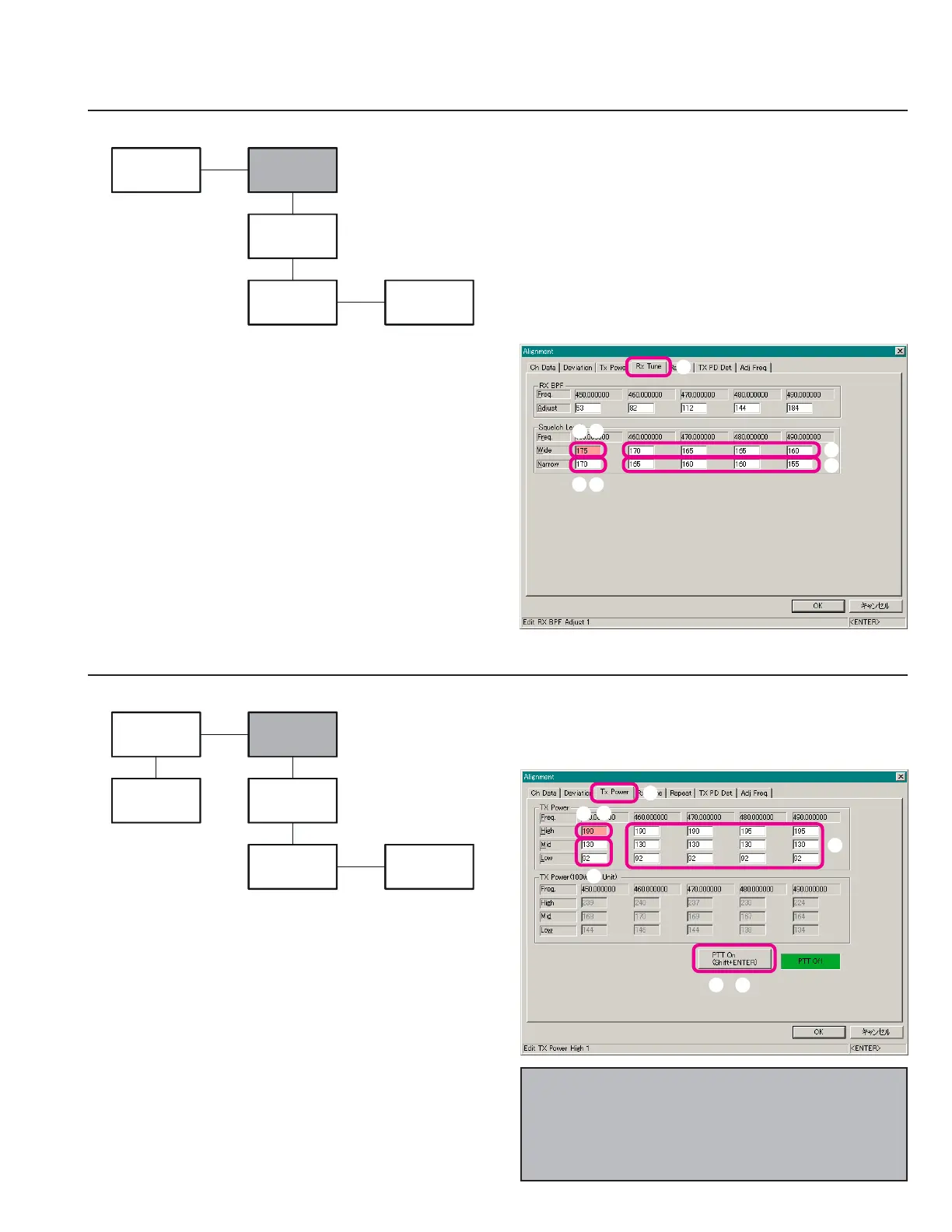
Open the “Alignment” window, then click the left
mouse button on the “Rx Tune” tab to move to the “Rx
Tune” screen.
Click the left mouse button on the “Wide” box on the
“Low Band Edge Frequency” area of the “Squelch
Level” field (highlighted in “pink”).
Set the RF Signal Generator output to the “Low Band
Edge” Frequency, at a level of –3 dBμV, ±3.0 kHz de-
viation with a 1 kHz audio tone.
Press the
[
Page Down
]
key until the squelch close, then
press the
[
Page Up
]
key to the point where the squelch
is just opened.
Repeat above steps at the other four points (box: fre-
quencies).
TX Power
Open the “Alignment” window, then click the left
mouse button on the “Tx Power” tab to move to the
“Tx Power” screen.
Click the left mouse button on the “High” box on the
“Low Band Edge Frequency” area of the “TX Power”
field (highlighted in “pink”).
Click the left mouse button on the “PTT On” button to
actitvate the transmitter (the “PTT On” label is changed
to “PTT Off”).
Press the
[
Page Up
]
/
[
Page Down
]
key so that the
Power Meter reading is 50 W.
Click the left mouse button on the “PTT Off” button
to disable the transmitter (the “PTT Off” label is re-
turned to “PTT On”).
Repeat the above steps at the “Mid” (25 W) and “Low”
(10 W) boxs.
Repeat the above steps at the 12 points (box: frequen-
cies).
Click the left mouse button on the “Narrow” box on
the “Low Band Edge Frequency” area of the “Squelch
Level” field (highlighted in “pink”).
Set the RF Signal Generator output to the “Low Band
Edge” Frequency, at a level of –3 dBμV, ±1.5 kHz de-
viation with a 1 kHz audio tone.
Press the
[
Page Down
]
key until the squelch close, then
press the
[
Page Up
]
key to the point where the squelch
is just opened.
Repeat the above steps at the four points (box: frequen-
cies).
Setup the test equipment as shown below.
Note: When the optional 100 PA Unit is installed, per-
form this adjustment parameter in the “TX Power (100
W Unit)” field. In this case, adjust the “High” power to
“100 W,” “Mid” power to “50 W,” and “Low” power to
“25 W.”
RF Signal
Generator
Computer
(
CE60
)
VXR-9000
FRB-6
MIC
USB Port
RX ANT
FIF-10A
or
FIF-12
50-ohm
Dummy Load
Inline
Wattmeter
Computer
(
CE60
)
VXR-9000
FRB-6
MIC
USB Port
TX ANT
FIF-10A
or
FIF-12
 Loading...