VERTIDRIVE B.V. | GIETERIJWEG 15 | 3089 JZ ROTTERDAM | THE NETHERLANDS - 30 -
T +31 (10) 763 02 00 | E SALES@VERTIDRIVE.COM | W WWW.VERTIDRIVE.COM
CHAMBER OF COMMERCE 24448205 | VAT NL 8201.77.064.B01
In all cases where we act as provider or supplier, our offers, orders placed with us, and agreements concluded with us are subject to the conditions and requirements laid down by the Netherlands Metal Association (the ‘Metaalunievoorwaarden’).
These conditions and requirements are filed with the registrar of the District Court of Rotterdam.
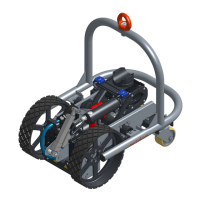
4. Magnetism will directly hold the robot in place
on the surface. Robot frame can now be
released.
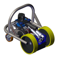
5. Rotate the lever in CW direction to lower the
rear magnet to the working position. Guide the
handle throughout the entire motion to ensure
a smooth transition.
Avoid entrapment of hands and / or fingers!
To remove the robot from the surface, lift the rear magnet to the highest position and follow the steps above in the
opposite order. Make sure the application (swing arm) is removed from the robot before removal, otherwise the robot
will not be able to rotate sufficiently to detach from the wall.
8.1.3. Connection and application setup
Once the robot is placed on the surface, the application (swing arm) can be mounted on the robot and the umbilical
cable connected:
1. Mount the swing arm with application to the robot (see application manual for details).
2. Unroll the entire umbilical cable to allow for free movement of the robot.
3. Remove the protection caps from the connectors (robot and umbilical cable).
4. Tilt the connector on the robot up and insert umbilical cable connector. Important: tilt the connector
maximum 45°. Larger angles can damage the cable on the robot.
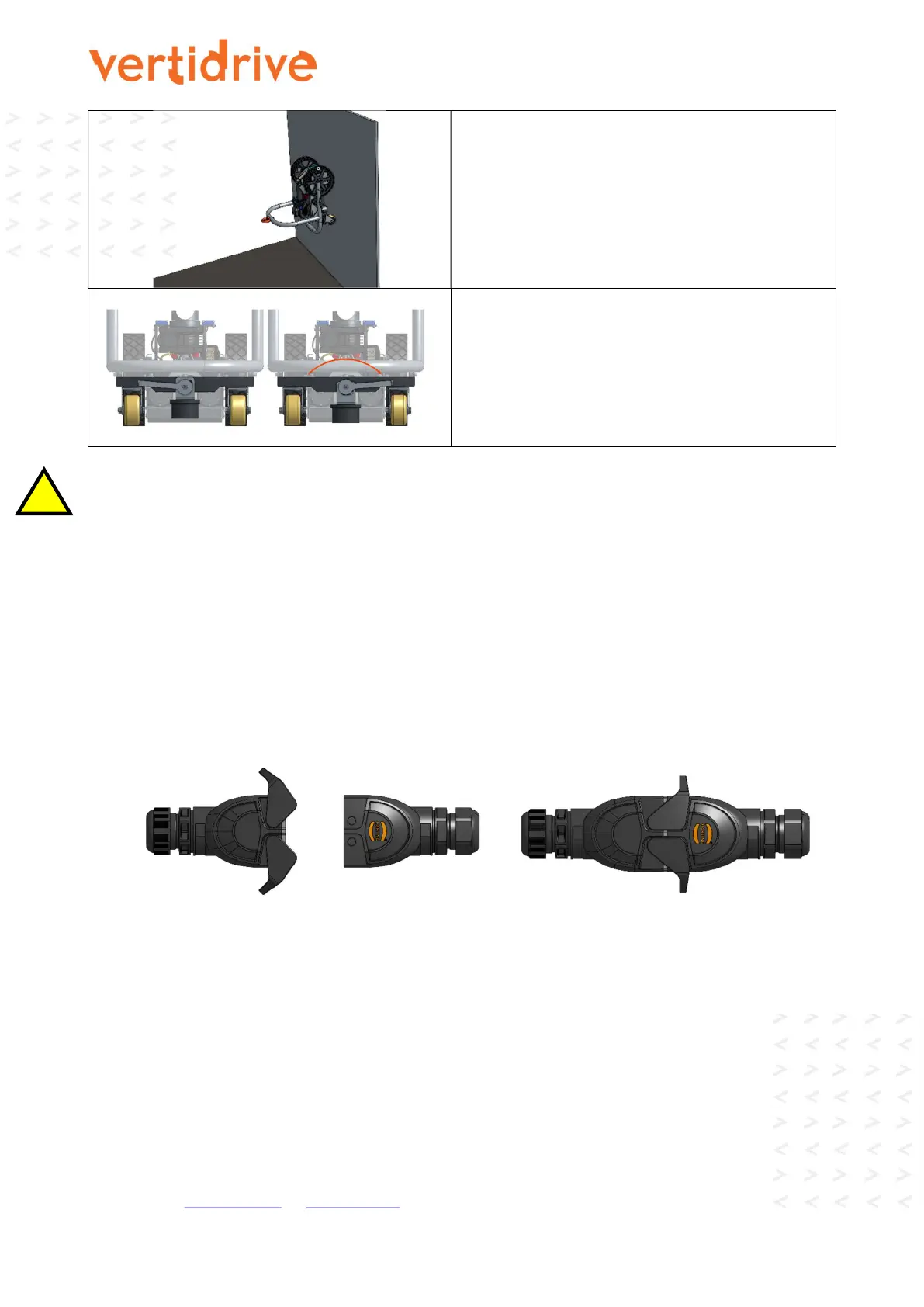
5. Connect the male and female connector and close the locking levers as shown below. In the correct
orientation, the pin on the tension relief is facing the side plate.
6. Carefully position the umbilical cable within the robotic frame, parallel to the side plate.
7. Put the pin on the tension relief through the hole in the side plate and secure with the locking pin as shown
in the picture below.
 Loading...