VERTIDRIVE B.V. | GIETERIJWEG 15 | 3089 JZ ROTTERDAM | THE NETHERLANDS - 32 -
T +31 (10) 763 02 00 | E SALES@VERTIDRIVE.COM | W WWW.VERTIDRIVE.COM
CHAMBER OF COMMERCE 24448205 | VAT NL 8201.77.064.B01
In all cases where we act as provider or supplier, our offers, orders placed with us, and agreements concluded with us are subject to the conditions and requirements laid down by the Netherlands Metal Association (the ‘Metaalunievoorwaarden’).
These conditions and requirements are filed with the registrar of the District Court of Rotterdam.
8.1.4. Robot operation
This section describes the required steps for robot operation. Always keep a safe distance of minimum 6 meters from
the robot when activating and operating the robot.
Startup
1. Power on the system by using the main switch on the control box.
2. Turn on the remote control by rotating the black knob to the “on” position. The remote takes several seconds
to start up and establish communication with the receiver. Two short beeps and a fast-blinking green light
on the remote control will indicate when the connection is ok.
3. Activate the remote control by pressing the green button on the right side. Note that for safety reasons,
system activation is only possible when all power functions on the remote are off:
a. Swing arm control: off
b. Step control: off
c. Pump: off
d. Swing arm up / down: off (neutral position)
e. Joystick robot control: inactive (neutral position)
f. Joystick winches control: inactive (neutral position)
4. Check indicator lights on the control box for system status:
a. Green light (constant on): indicates the control system is powered.
b. Yellow light (constant on): indicates that the control system is activated and the safety circuit of the
WCS is closed; all robot functions are operational.
c. Orange light (blinking): indicates that the control system is activated, but the safety circuit of the
WCS is not closed; only the non-safety critical functions of the system are operational (but the robot
drives and swing arm, as well as the pump / valve control, will not work).
d. Red light (constant on): indicates that a fault is detected in one or more motor drive(s), and the
corresponding motor on the robot will not function (correctly). Restart the control system by turning
the main switch to “off”, wait for 30 seconds and turn the main switch to “on”. If restarting does not
solve the problem, refer to chapter 10, troubleshooting.
Basic operation
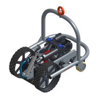
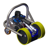
The V700 Series robot has multiple functionalities, that are briefly explained in this section. The numbers used refer to
the controls as indicated in chapter 6, section 6.4:
Drive
o The robot is moved across the surface using the joystick (8) on the right side of the remote control.
The joystick controls both the speed of the robot and the direction.
o The maximum driving speed of the robot can be set using the speed control knob (7).
o If the robot deviates from a straight line due to uneven loads on the robot (most often caused by
the umbilical cable and hoses pulling on the robot at an angle), the adjust knob (9) can be used.
This function compensates either the left or right drive speed, to achieve the desired straight line.
This function is particularly useful when driving horizontally across the surface.
o For optimal application process control, the step time control (5) is used. When selected, the robot
will drive a specific distance forward between swing arm sweeps. While the swing arm is performing
the application (within the effective range of the swing arm) the robot will not move forward. This
function results in a very effective and constant application pattern on the surface. The step time
control has two settings, depending on the required distance between application sweeps: the slow
setting allows maximum 10cm (4”) movement between sweeps, the fast setting allows 20cm (8”)
movement. It is recommended to use the slow setting whenever possible and only switch to the fast
setting when more than 10cm distance between sweeps is required for the application.
 Loading...