Chapter 6 Connection diagram
The diagrams illustrated here are examples of Virtual Matrix KVM over IP, the actual applications may vary. All
illustrated computer, accessories and monitors are not included in the package, it is for reference only. Make sure all
the devices and peripherals are connected appropriately before using this unit.
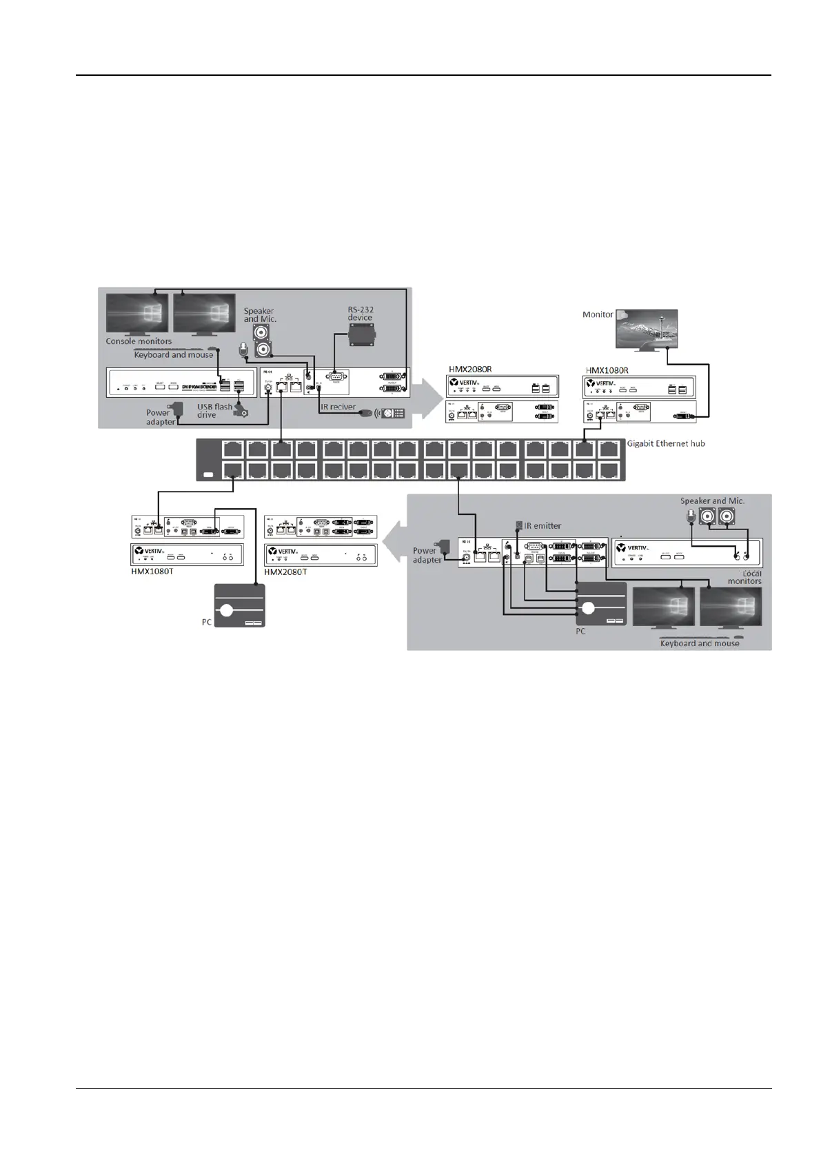
Based on the same series, the mixed connection can be supported, for example, HMX1080 transmitter connects to
HMX2080 receiver. Besides, you can select to install the KVM directly or via a Gigabit Ethernet Hub/Switch depends
on your requirement.
Figure 6-1 Connection diagram
6.1 Before connection
Before you install the Virtual Matrix KVM over IP, you should have these items on the checklist ready:
Plan the layout path and deploy the UTP cable for extension.
Plan the path through which the CAT6 UTP cable (or higher category network cable) will be deployed across the
distance between the Transmitters and the Receivers. You should choose the layout path not only based on shortest
possible length consideration, but also on least electromagnetic interference.
Notes:
Use good quality CAT6 cable can be produced the better video outcome with longer distance span.
The ideal location for the power outlets near where you located the extenders.
6.2 Direct connection
Basically, you can extend the signal using a connection of point-to-point via a CAT6 cable. Based on your
requirement, you can also connect the transmitter to multiple receivers and vice versa. Each point can be supported
the unit up to 4.