Mechanical Installation
Vertiv | Liebert CRD10 | User Manual 34
3.5 System Installation Layout
The installation modes of the CRD10 unit are shown in Figure 3-8 and 3-9.
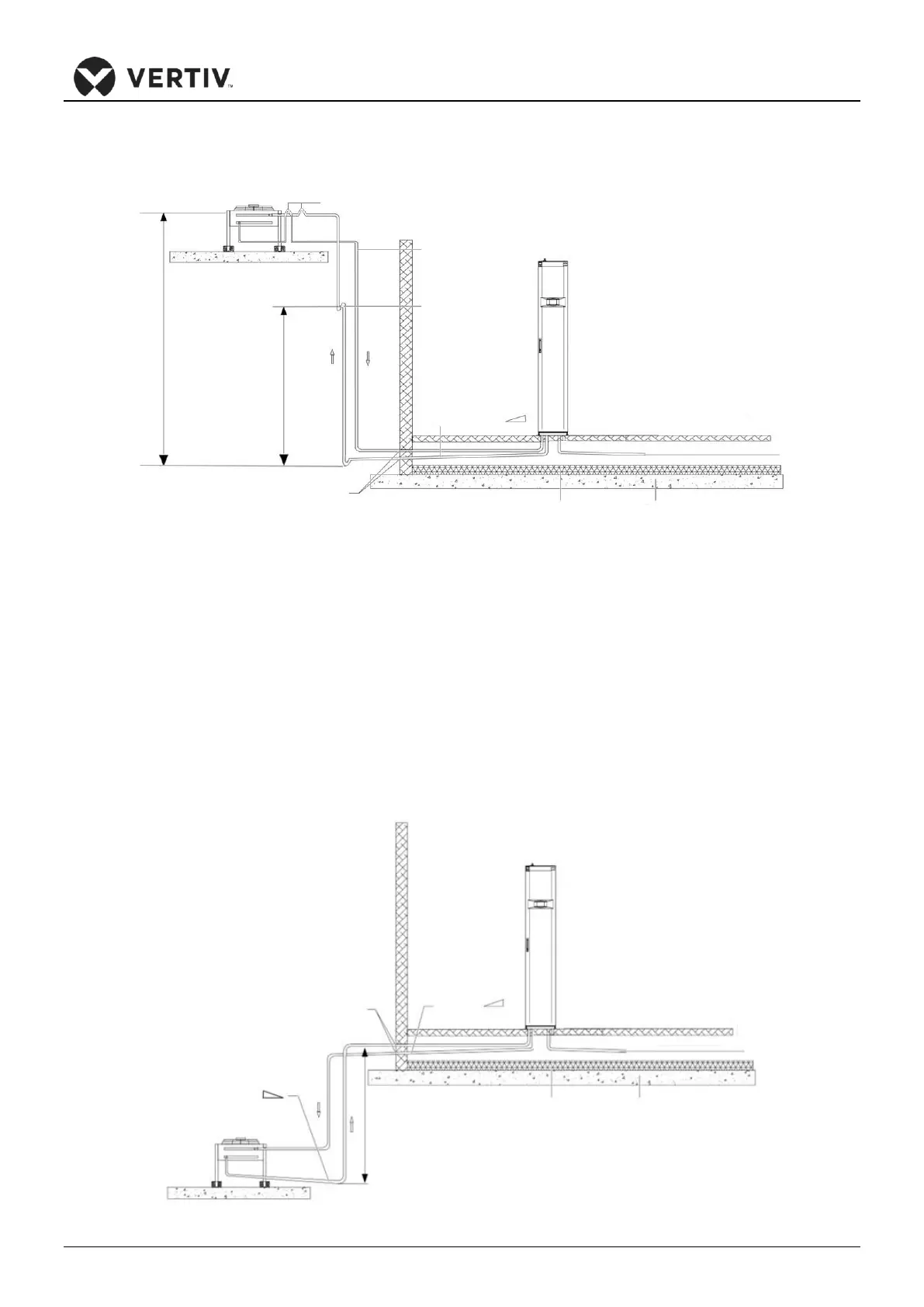
Figure 3-8 Condenser is Placed Higher than the Compressors during Installation
In Figure 3-8, the condenser is installed higher than the compressor. Therefore, an inverted trap is fitted to the
discharge line and the liquid line of the condenser. The inverted trap is essential as it helps prevent the liquid
refrigerant from flowing back once the condenser stops. The top end of the inverted trap must be installed
higher than the ultimate level of the copper pipe of the condenser. Recommended the minimum height
difference is 150mm (5.9in.). A trap must be installed every 7.5m(24.6ft.) of the vertical discharge line.
However, if the condenser is installed lower than the compressor, then no modification is required. Figure 3-9
shows the schematic diagram of system installation when the condenser is installed at a lower level than the
compressor. If using low ambient kit when mounting condenser below level of the indoor unit, the allowable
height refers to Table 3-5.
Figure 3-9 The Condenser is Lower than the Compressor during Installation