22 VERTIV™ - Liebert
®
EFC - UM - 10040805MAN_ENG - 30.03.2023
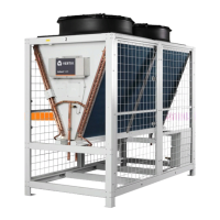
The condensing coil, installed inside the fan module is delivered
nitrogen-pressurized at 2 bar. In case of remote condenser installation,
the air condensing units are delivered nitrogen-pressurized at 2 bar.
The discharge operation of the heat
exchanger module unit pressurized with nitrogen
(at 2 bar) and the unbrazing of the bottoms from the
connections must be carried out as last operations,
immediately followed by the connection and emptying
of the whole system. During brazing operation, protect
components around from superheating/damaging.
For the standard unit with the condensing coil installed inside
the fan module, the piping to do the refrigerant connections are
supplied with the unit. In case of remote condenser installation
follow the steps below:
1. In soft or hard copper. The diameter required is stated in Tab. 5.1.
If the installer intends to use pipes of a larger diameter (e.g.
for long winding runs) then consult Technical Sales Support.
Use as short refrigeration pipelines as possible to minimize
the total charge of refrigerant and the pressure drops. Lay the
horizontal gas pipes with 1% downward gradient towards the
2. Reduce the number of bends, which must be of large radius,
to a minimum.
3. Insulate the piping. If the pipes are put next to the electrical
cables it is advised to insulate them to avoid damage to cable
insulation.
4. There must be a minimum separation of 20 mm between the
gas and liquid pipelines. If this is not possible insulate both
lines.
5. Support both horizontal and vertical pipes with vibration-
damping clamps (which include rubber gaskets). Place these
every 1.5 - 2 m.
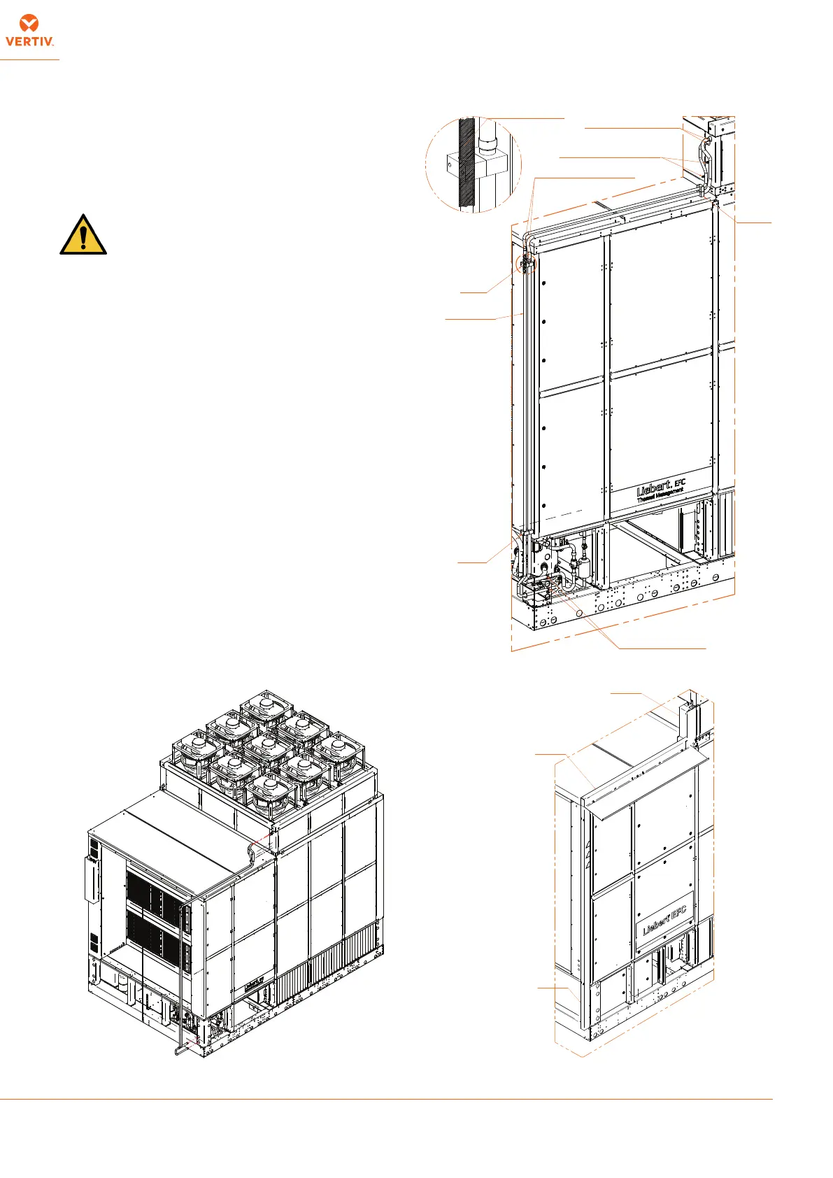
DET. B
INSULATION:
APPLY CLAMP ABOVE INSULATION
FOR PIPE DIAM 18 AND 22 mm
SOLDER TYPE 5% Ag
REFRIGERANT
CONNECTIONS
SCHRADER VALVE
WITH CAP AND GASKET
SOLDER TYPE 5% Ag
SOLDER TYPE 5% Ag
B
CLAMP
CLAMP
CLAMP
COVER
COVER