24 VERTIV™ - Liebert
®
EFC - UM - 10040805MAN_ENG - 30.03.2023
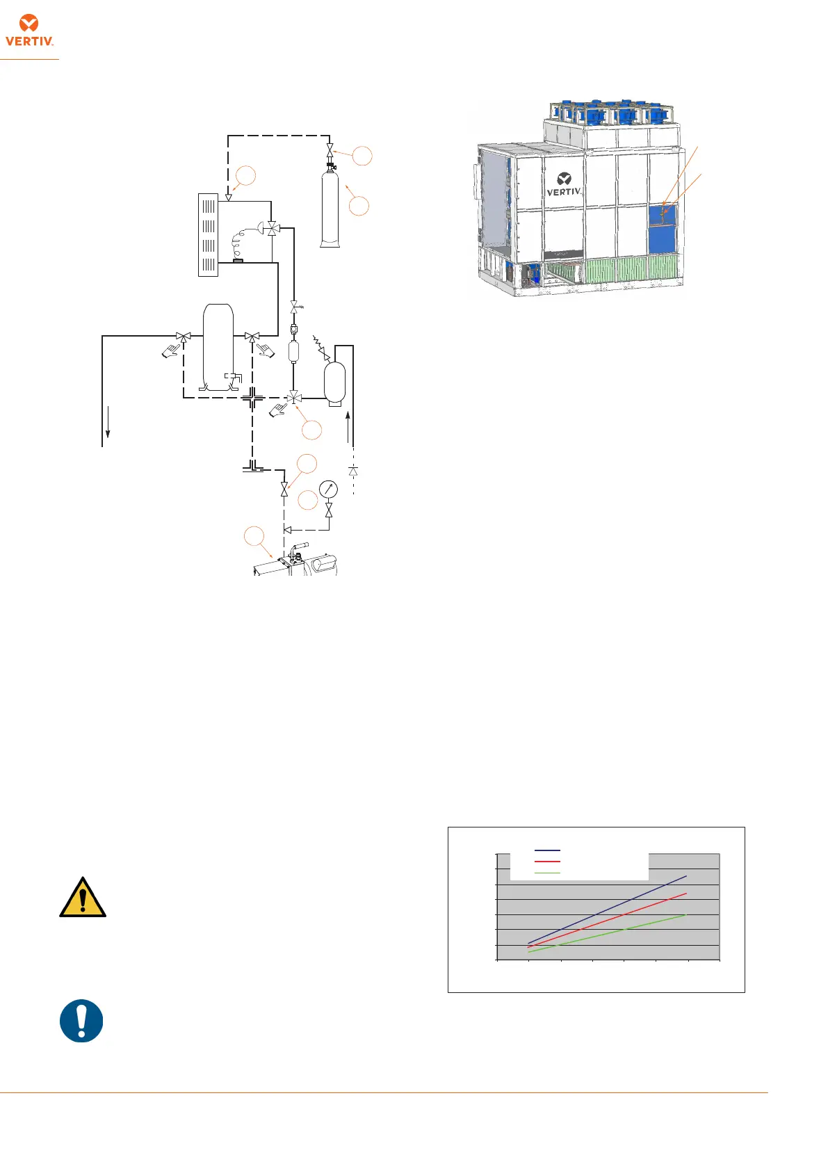
1. Open all valves of the system including those used for
pressurizing and energize the solenoid valve. With this
operation all the components of the refrigerant circuit are
subjected to vacuum.
2. 10) suitable
for polyester oils to the couplings:
• Compressor intake and delivery using the 5/16" Schrader
valves welded on the piping.
• Schrader coupling (12
3. Provide for a connection with refrigerant cylinder before
making vacuum.
4. Make the system vacuum up to 0.3 absolute mbar and after
hours check if 1.3 absolute mbar have not been exceeded.
This condition ensures a humidity lower than 50 ppm inside
the system. If the complete vacuum is not possible, this means
that there are some leaks (to be removed according to the
instructions in 6. below). The additional oil charge is already
charged in factory. Check the right oil level in sight glass during
the commissioning (see 8.1). If the level is too low see 9.6.2.
5. Break the vacuum as follows:
a. Close the valve (10a) for the vacuum pump (10).
b. Open the valve of the refrigerant cylinder (11a) until the
system reaches a pressure value of about 1 bar.
The refrigerant must be introduced and
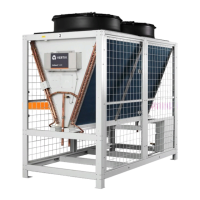
With low ambient kit, remove low ambient kit external panel to reach
the TXV.
c. At this point both the vacuum pump and the refrigerant
cylinder can be disconnected as follows:
c1. close the cylinder cock (11a)
c2. close the way 5/16" SAE of the connected Schrader valves.
6. Inspect all connections/joints using a leak detector. If a leak is
found, empty the pipes and the condenser, seal the leak and
repeat the instructions in 3. - 6.
7. Now the machine is ready for completing the charge and the
start-up.
8. Charge the refrigerant () by means of the charge
valve placed at the evaporator inlet.
1. Start the unit.
2. Manually start the compressor (when the unit is equipped with
tandem compressors start both of them), ensure the unit is not
3. Guarantee a constant condensing temperature (preferably
42°- 45°C); if necessary, partially obstruct the condenser coil
surface or limit its ventilating power to obtain these conditions.
4. Charge the unit until the working conditions of the entire
refrigeration circuit have become normal.
5. Using a manometer, check that the evaporating temperature
is above 0°C.
6. Verify that the superheat is 6-8 K.
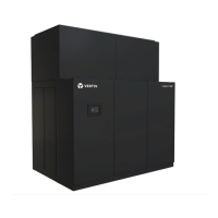
7.
condensing temperature and evaporating temperature at
then adjust the charge to match the target subcooling found
(subcooling should be measured at the expansion valve inlet).
With digital scroll compressor cooling systems, during the
charge adjustment, the compressors have to be at the full
capacity. Higher charge increases the subcooling value.
8. Verify the absence of bubble on sight glass.
The refrigerant circuits are presented in Enclosure C.
R.L .
10
10a
11
11a
13
12
10b
(*) only with reheating coil (optional)
Condensing temperature [° C]
subcooling [K]
Liebert® EFC
0
2
4
6
8
10
12
14
25 30 35 40 45 50 55 60
8÷12 ° C evap. temp.
12÷15 ° C e vap. temp.
15÷20 ° C e vap. temp.