32 VERTIV™ - Liebert
®
EFC - UM - 10040805MAN_ENG - 30.03.2023
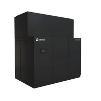
the name plate. Always use appropriate ports provided on the unit
for cable passage way. Refer also to electrical diagram supplied
with the unit.
Unit ground connection should be made using the appropriate
terminals provided outside the unit, with cables of adequate
section and carefully following all procedures and standards.
Grounding of the unit is a fundamental requirement to comply
with safety codes against electrical/electrostatic accidents.
All cables and connections of electric parts should comply with the
current IEC standards, or the standard national requirements of
the country.
• It is mandatory to install an external main switch ON site easy
to reach, to facilitate a quick and easy shutdown enabling the
power of the unit to be cut OFF.
Refer to the unit electrical schematics for the installation. Follow all
local codes.
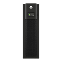
If the unit is installed above some support, some electrical
components will result higher: use a ladder to compensate the
increased height.
Refere to pictures below for electrical connections path for ,
and
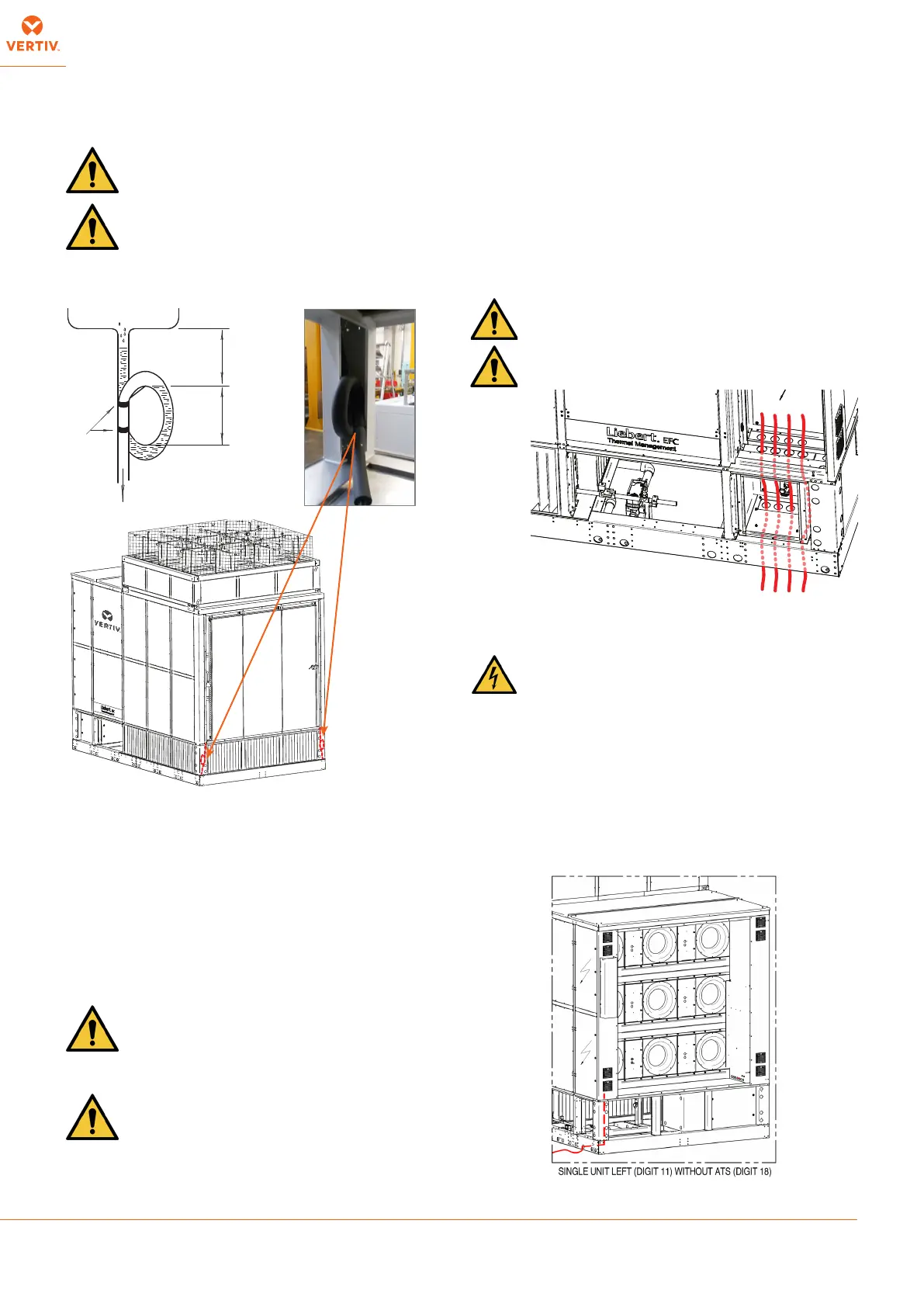
The water and drain connections of the Liebert
®
unit are presented in the picture below.
the unit is supplied with 2 traps placed on
condensate drain panel bottom. The condensate is discharged on
unit basin. Fill in the drain trap with water before unit start-up.
dimensions of those existing on the central station unit and
indicated on the general drawing supplied (see Enclosure B);
all screws supplied must be used and sealing gasket should be
interposed. Install antivibrating joints between duct and unit, to
avoid vibration transmission.
installation to access to temperature/humidity sensors
(see positioning drawing)
It’s strongly recommended to have some engineers
supervising this phase, in order to have connections
done properly and completed without mistakes.
The unit name plate and the literature supplied with the unit show
the electric features and the maximum full-load current input of all
BRACKET
min.
200 mm
min.
100 mm
The evaporative system doesn’t work when the external ambient
temperature is low (near water freezing point).
Ensure there is no risk of freezing on water traps and
on evaporative system water feeding and discharge line.
The unit must be periodically cleaned/disinfected using
liquid that must be recovered. We suggest to prepare
the discharge line ready to receive the liquid used for the
cleaning/disinfection.