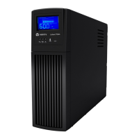
3.2.6 Load Transfer 1+N System:Add a UPSto the System (Collective)
To add one UPS module to the collector bus:
NOTE: A load drop will occur if the UPS modules supporting the load are in Bypass Mode and control power is applied
to the offline module (assuming that paralleling cables are installed in the offline module when control power is
turned On).
1. Verify that all parallel cables are properly connected to the UPS units.
2. Close the external rectifier feeder breaker on the UPS module to be added to the system.
• External Remote Back-Feed Breaker (RBB) for single input/feed applications
• External Rectifier Feed Breaker (RFB) for dual input/feed applications
NOTE: The Rectifier will start the UPS module at this time. Do not proceed until the Touchscreen Control Panel is fully
operational on the UPS module.
3. Verify that the rectifier on the UPS module has started. The rectifier icon on the Touchscreen Control Panel
should be Green. If it is not, the issue must be corrected before proceeding.
4. Close the external Remote Back-Feed Breaker (RBB) if installed.
5. Verify that the Bypass Static Switch (BPSS) on the UPS module is Off. If it is not, the issue must be corrected
before proceeding.
6. Close the external Module Battery Disconnect(s) (MBDs) on the UPS module.
7. Close the external Module Output Breaker (MOB) on the UPS module.
8. Verify that the inverter on the UPS module is active. If the inverter does not start, touch the on/off button
located on the overview screen, then select start inverter.
9. Verify that all inverters are connected to the collector bus.
3.2.7 Load Transfer 1+N System—Transfer System Inverter to Bypass
To transfer the UPS system from Inverter Mode to Bypass Mode:
NOTE: The critical load should be on the UPS Inverter.
1. From one of the UPSs' Touchscreen Control Panel, touch the on/off button located on the overview screen.
2. When prompted by the Touchscreen Control Panel, select stop inverter.
3. Repeat steps 1 and 2 on each UPSs' Touchscreen Control Panel.
4. The load should be on UPS bypass at this time.
NOTE: The load will now be on static bypass in each UPS.
3.2.8 Load Transfer 1+N System:Transfer System from Bypass to Inverter
To transfer the UPS system from Bypass to Inverter mode of operation:
NOTE: The critical load should be on the UPS Bypass.
1. From one of the UPSs' Touchscreen Control Panel, touch the on/off button located on the overview screen.
2. When prompted by the Touchscreen Control Panel, select start inverter.
3. Repeat steps 1 and 2 on each UPSs' Touchscreen Control Panel.
4. The load should be on UPS inverter at this time.
3 Operation
25
 Loading...
