7. For control connection details, see Control Cabling on page 19.
8. Close and secure the interior and exterior doors.
9. Attach the kick plates to the bottom of the unit.
NOTE: If the unit will be installed in a position that does not permit access to rear kick plates, then the kick plates
must be installed before the unit is placed in its final position.
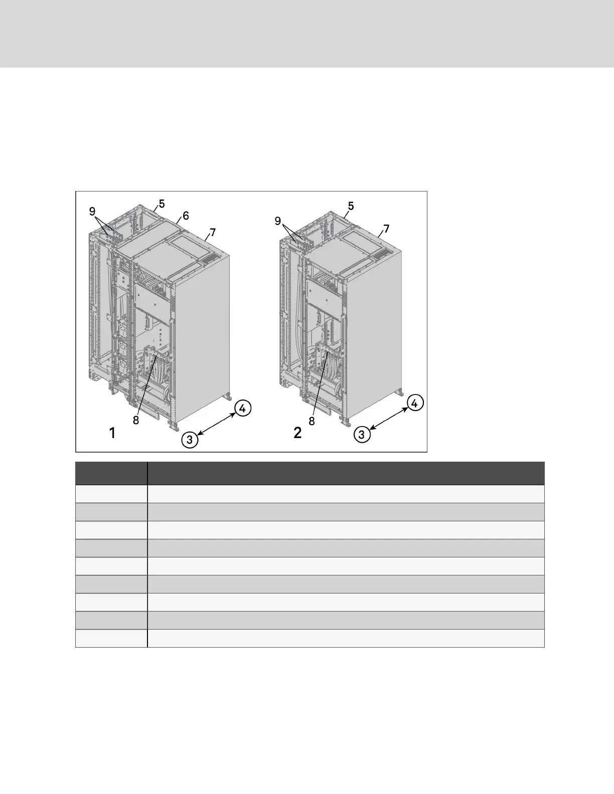
Figure 3.4 Attached battery cabinet busbar connections toEXL S1 250-600kVA
Item Description
1 EXL S1 250-600kVA withbackfeed disconnect or sharinginductors
2 EXL S1 250-600kVA without backfeed disconnect or sharing inductors
3 Rear of cabinet
4 Front of cabinet
5 Battery wiring cabinet
6 Backfeed disconnect and/or sharing inductor inputI/output cabinet
7 Standard inputI/output cabinet
8 UPS inputI/output cabinet positive and negative busbars
9 Battery cabinet positive and negative busbars
Vertiv | Liebert® Large UPS Battery System Installer Guide
16