Vertiv™ NetSure™ 7100 Series -48 VDC Power System User Manual
8. For a system installed in a relay rack, replace the rear covers onto the expansion module mounting assembly and the module
mounting assembly installed directly above it.
9. Refer to the Power System Installation Instructions (IM582127000) and connect AC input power to the expansion module
mounting assembly.
10. For a system mounted in an enclosure, replace the rear covers.
11. Refer to the Rectifier Instructions and install rectifier modules into the expansion module mounting assembly as required.
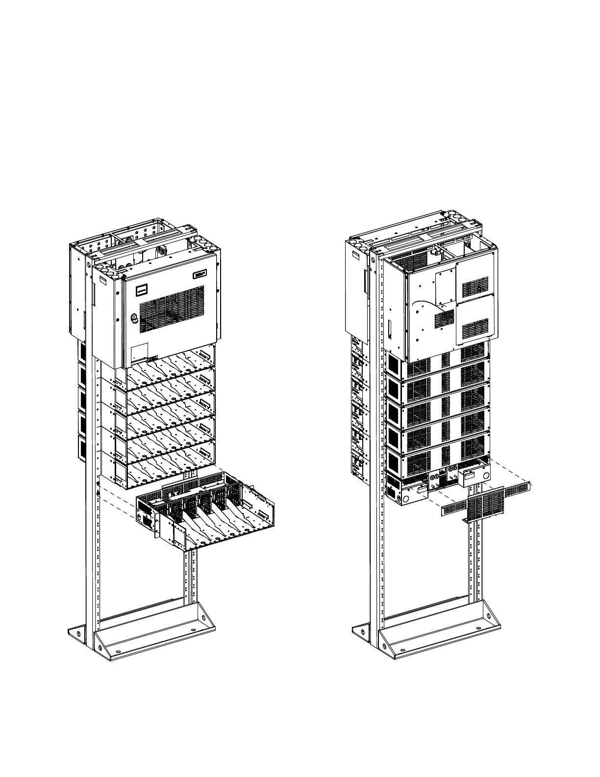
Figure 4.4 Installing a Field Expansion Module Mounting Assembly Spec. No. 588705000 or 588705500 (cont’d on next page)
Front View
(Install Expansion
Module Mounting Shelf)
Rear View
(Remove Rear Shield from
Module Mounting Shelf
and Shelf Above It)

 Loading...


