Vertiv™ NetSure™ 7100 Series -48 VDC Power System User Manual
4.8 Changing the Controller’s LVD Control Level for a Contactor
The controller has two available LVD control levels (LVD1 and LVD2). The level used to control a contactor is determined by which
connector on the LVD circuit card its control leads are plugged into. To change the LVD control level for a contactor, simply switch
which LVD connector it is plugged into (if an open connector is available) on the LVD circuit card. Refer to Figure 5.20 and
Figure 5.21 for connector location and function.
NOTE!
DO NOT change a Low Voltage Load Disconnect contactor to LVD Control Level 2 (LVD2) if the system is furnished
with a Low Voltage Battery Disconnect contactor.
4.9 Adding a Supplemental Bay in the Field
Refer to the Power System Installation Instructions (IM582127000) for procedures detailing mounting and wiring of the supplemental
bay.
Supplied with the supplemental bay is a USB drive which contains the product documentation along with a document file that
provides a listing of the SM-DU and optional SM-DU+ settings required for that particular supplemental bay. See Table 4.3 and
Table 4.4
for samples of the information provided in the file. Refer to this document file (chart) and program the SM-DU and optional
(if furnished) SM-DU+ settings in the controller with the specific values listed in the chart. Refer to the NCU Instructions
(UM1M830BNA) for programming details. There are also labels located near the SM-DU and SM-DU+ in the supplemental bay that
detail the controller’s settings for this bay.
The controller must be rebooted after connection of the supplemental bay to configure the SMDU and SMDU+ (if equipped) in the
supplemental bay into the controller.
Reboot the Controller
Local Menu Navigation: At the Main Screen, press ENT and ESC at the same time to reset the NCU Controller.
Web Menu Navigation: Go to Advance Settings Menu / SW Maintenance Tab / Reboot Controller button.
Once the controller has been programmed for the newly installed supplemental bay, refer to the NCU Instructions (UM1M830BNA)
and save a copy of the “SettingParam.tar” file.
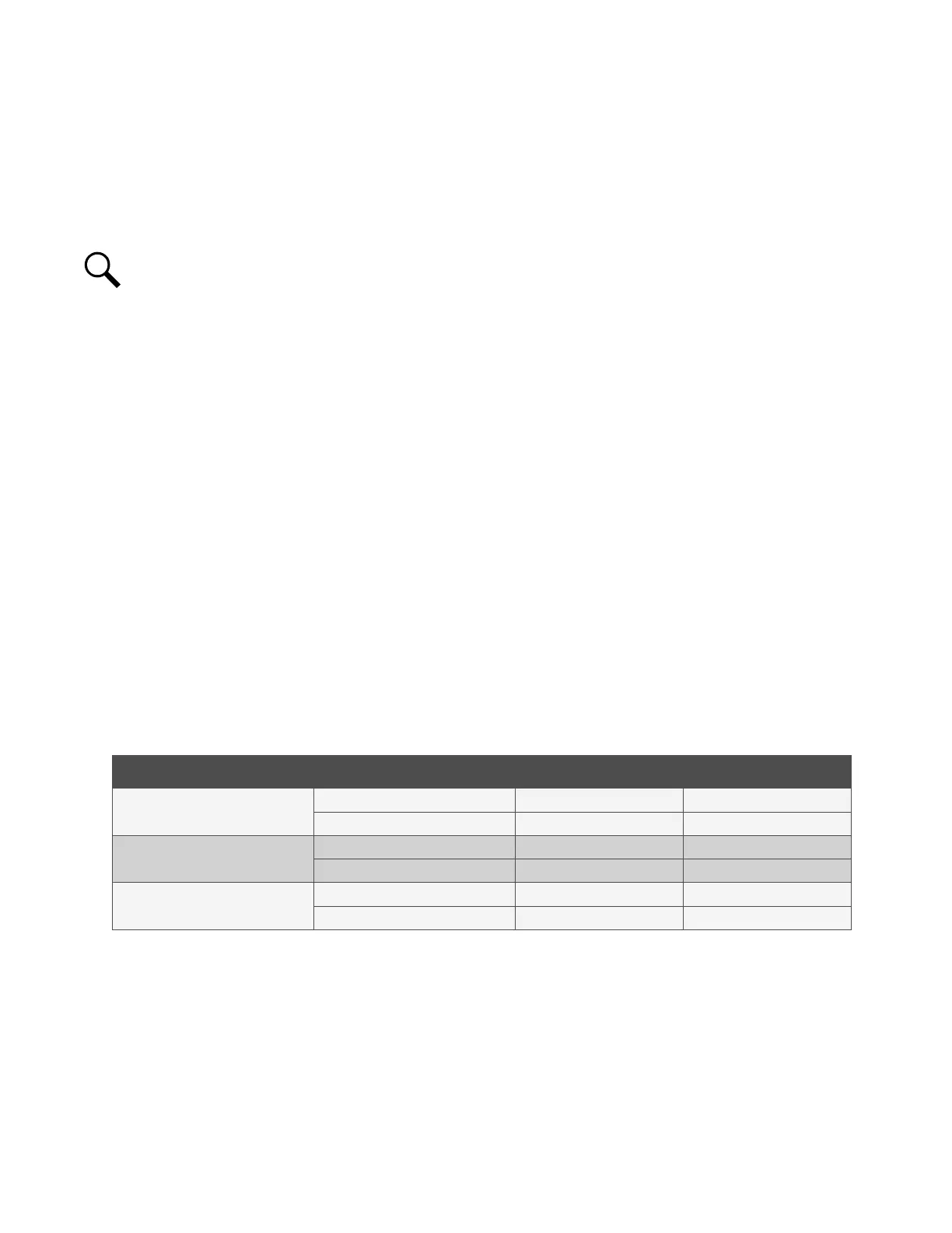
Table 4.3 Sample Supplemental Bay SM-DU Programmable Parameter Chart
Device Parameter Factory Setting Setting for this Bay
SM-DU Shunt 1 Load
Full Scale Current (A) 2500 Refer to USB Drive
Full Scale Voltage (mV) 25 Refer to USB Drive
SM-DU Shunt 2 Battery
Full Scale Current (A) 2500 Refer to USB Drive
Full Scale Voltage (mV) 25 Refer to USB Drive
SM-DU LVD
LVD1 Enabled Refer to USB Drive
LVD2 Enabled Refer to USB Drive

 Loading...


