Vertiv™ NetSure™ 7100 Series -48 VDC Power System User Manual
4.3 Adding a Rectifier or Converter Module to an Existing Spec. No.
588705300 Module Mounting Assembly
To increase system current capacity, a rectifier module can easily be added to an existing Spec. No. 588705300 module mounting
assembly that contains an empty rectifier module mounting position. Likewise, to increase subsystem capacity a -48 VDC to
+24 VDC DC-DC converter module can be added to a Spec. No. 588705300 module mounting assembly that contains an empty
-48 VDC to +24 VDC converter module mounting position. A -48 VDC to -58 VDC DC-DC converter module can be added to a
module mounting shelf that contains an empty -48 VDC to -58 VDC converter module mounting position.
Rectifier and converter modules can be inserted or removed with power applied (hot swappable).
Rectifiers modules can be installed in any mounting position of each module mounting assembly. Converters modules can be
installed in any of the three far right mounting positions of each module mounting assembly (as viewed from the front). See
Figure 4.3. See Alerts below for restrictions.
NOTE!
Each rectifier and converter module locks into the module mounting assembly by means of a latch located on the
bottom of the module. The latch and module handle are interactive. Pushing the handle up into the module’s front panel
causes the latch to extend to the locking position; pulling the handle down out from the module’s front panel causes the latch
to retract. See
Figure 4.3.
WARNING! To prevent damage to the latching mechanism, ensure the handle is in the open position when installing or
removing a module. NEVER hold the handle in the closed position when installing a module into a shelf.
ALERT! The system can either have +24V DC-DC converters installed or -58V DC-DC converters installed. The system
cannot have both types of converters installed at the same time.
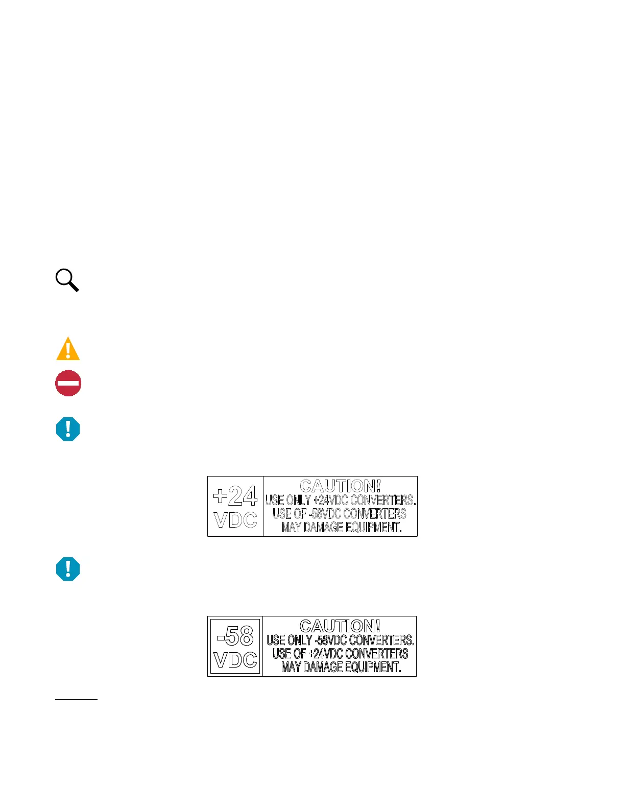
ALERT! The -48 VDC to +24 VDC converter modules must only be installed in a system position that accepts a +24V DC-DC
converter. Refer to labeling on the system’s module mounting shelf. A sample of this labeling is provided in Figure 4.1.
Figure 4.1 Sample Module Mounting Shelf Labeling
ALERT! The -48 VDC to -58 VDC converter modules must only be installed in a system position that accepts a -58V DC-DC
converter. Refer to labeling on the system’s module mounting shelf. A sample of this labeling is provided in Figure 4.2.
Figure 4.2 Sample Module Mounting Shelf Labeling
Procedure
1. Unpack the modules.
2. Note the model number located on the front of each module. Model numbers starting with the letter “R” are rectifier modules.
Model numbers starting with the letter “C” are converter modules.

 Loading...


