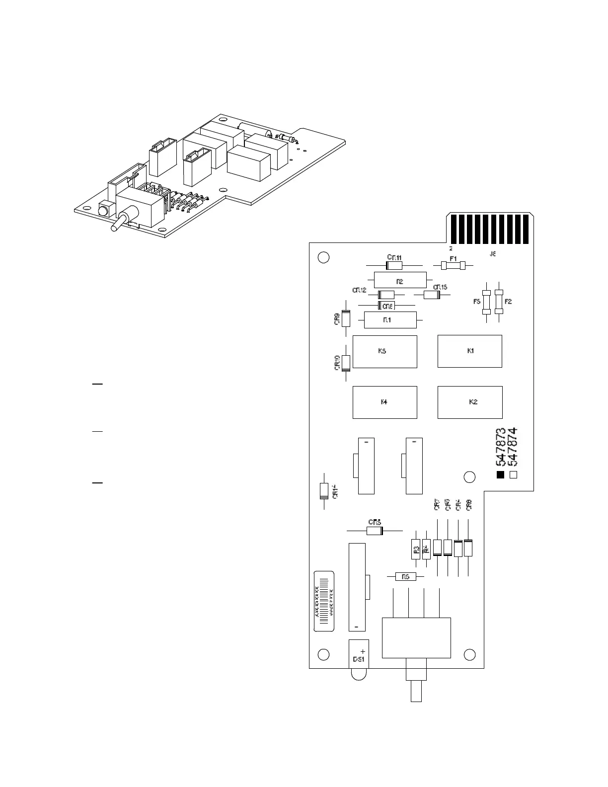
EasyManuals Logo

Vertiv NetSure 7100 Series User Manual

Vertiv NetSure
7100 Series
106 pages
To Next Page IconTo Next Page
To Previous Page IconTo Previous Page
Page #97 background imageLoading...
Page #97 background image
Vertiv™ NetSure™ 7100 Series -48 VDC Power System User Manual
87
Figure 5.21 Optional LVD Driver Lite Circuit Card Connector Locations
Notes:
1. Connects up to (2) LVD
contactors rated at 600A or less.
2. Only one (1) contactor per level
can be accommodated. J2 and J3
are on Level 2, only one (1) of these
connectors can be used at a time.
3. Switch and indicator located
on circuit card installed in
Main Bay only.
J1
To LVLD contactor, uses Controller
LVD1 control setting (Level 1).
J3
To LVLD contactor, uses Controller
LVD2 control setting (Level 2).
J2
To LVBD contactor, uses Controller
LVD2 control setting (Level 2).
Can only be used if it is contained
in a List 21 (1-row) cabinet.
J1J3
J2
S1
DO NOT change a Low Voltage
Load Disconnect contactor to
LVD Control Level 2 (LVD2) if
the system is furnished with a
Low Voltage Battery Disconnect
contactor.
Main Bay

Table of Contents

Other manuals for Vertiv NetSure 7100 Series

Questions and Answers:

Question and Answer IconNeed help?

Do you have a question about the Vertiv NetSure 7100 Series and is the answer not in the manual?

Vertiv NetSure 7100 Series Specifications

General IconGeneral
BrandVertiv
ModelNetSure 7100 Series
CategoryPower Supply
LanguageEnglish

Related product manuals