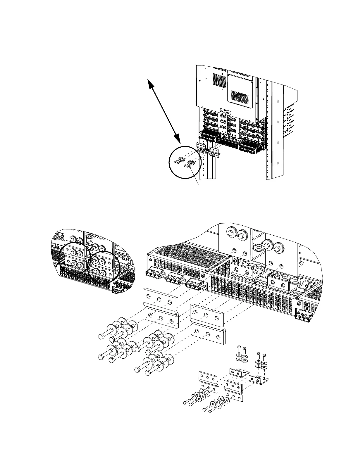
Apply electrical anti-oxidizing
compound to busbar mating
surfaces.
Rear
Remove this hardware from the lowest
module mounting assembly and re-use
it to add the busbar extensions for the
expansion module mounting assembly.
5. Remove hardware from the lowest
module mounting assembly’s
-48V and return busbars.
6. Install the busbars provided
with the expansion module
mounting assembly between
the assemblies, using the hardware
removed in the above step.
See Detail B.
7. After making CAN bus connections
(see next page), re-install the rear
busbar shield previously removed.
8. To add a second expansion module
mounting assembly, repeat this procedure.
Note that the lower section of the
center rear shield on the first
expansion module mounting assembly
needs to be removed from the rear
section of the shield. See Detail C.
1/4-20 x 1-1/4” Bolt
1/4” Belleville Lock Washer
1/4” Belleville Lock Washer
(concave side of Belleville
lock washers face each other)
1/4” Flat Washer
Torque to 60 in-lbs.
1/4-20 x 3/4” Bolt
1/4” Belleville Lock Washer
1/4” Flat Washer
Torque to 60 in-lbs.
Detail View B
Detail View C
Expansion Assembly
Busbar Extension
Components
Expansion module mounting
assembly busbar extensions
installed view.

 Loading...


