Vertiv™ NetSure™ 7100 Series -48 VDC Power System User Manual
15. Reboot the Controller
Local Menu Navigation: At the Main Screen, press ENT and ESC at the same time to reset the NCU Controller.
Web Menu Navigation: Go to Advance Settings Menu / SW Maintenance Tab / Reboot Controller button.
16. Enable the external alarms or notify appropriate personnel that this procedure is finished.
17. Ensure that there are no local or remote alarms active on the system.
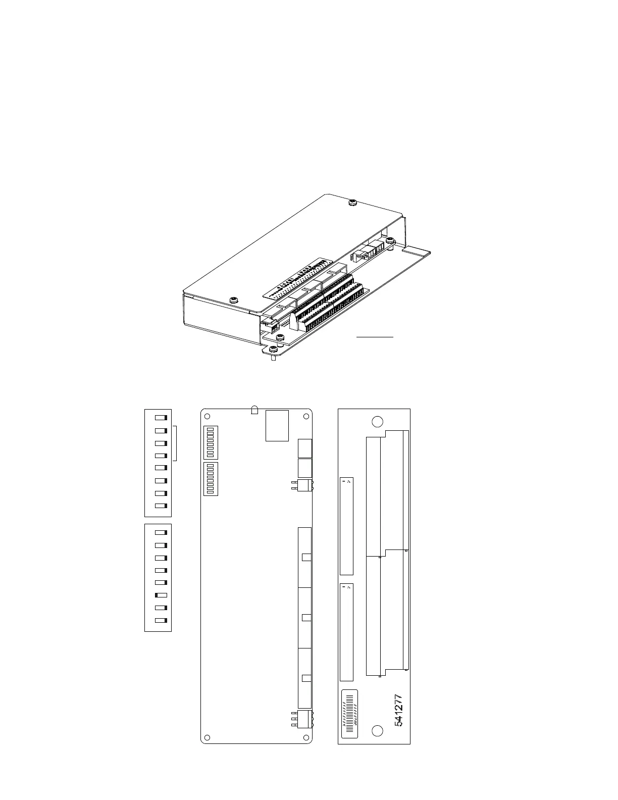
Figure 5.18 SM-DU+ and Shunt Interface Assembly Connector Locations
TB1 - TB2
Wire Size Capacity: 16-26 AWG.
Recommended Torque: 2.2 in-lbs.
SM-DU+ and
Shunt Interface Board
Shunt Interface BoardSM-DU+
1A
1B
TB1 TB2
J2J1
SW1 SW2
on
5 6 7 8
1 2 3 4
off
on
5 6 7 81 2 3 4
off
SW1 and SW2
In this system, switch settings
must be in the positions shown,
except adressing switches, which
must be set to a unique address.
Set each SM-DU+ in
the system to a unique
address.
SM-DU+ Circuit Card
Power CAN RS485 RS485
RS232
SW1 SW2
J1
J7
Shunt Shunt
J8 J6
Fuse
J3
J4 J4A
J5
ON
OFF
1 2 3 4 5 6 7 8 1 2 3 4 5 6 7 8
Green Indicator

 Loading...


