EasyManuals Logo

Vertiv NetSure 7100 Series Installation And User Manual

Vertiv NetSure
7100 Series
22 pages
To Next Page IconTo Next Page
To Previous Page IconTo Previous Page
Page #18 background imageLoading...
Page #18 background image
Vertiv™ NetSure™ Supervision Module for Distribution Unit Plus Installation and User Manual
12
Figure 4.4 Vertiv™ NetSure™ SM-DU+ Assembly CAN Bus Connections
To power system’s
CAN L Terminal.
To power system’s
CAN H Terminal.
Screw: #6-32 Philslot
Recommended Lug: #6 Spade
Distance between Barriers: 0.30”
Torque: 9.0 in-lbs.
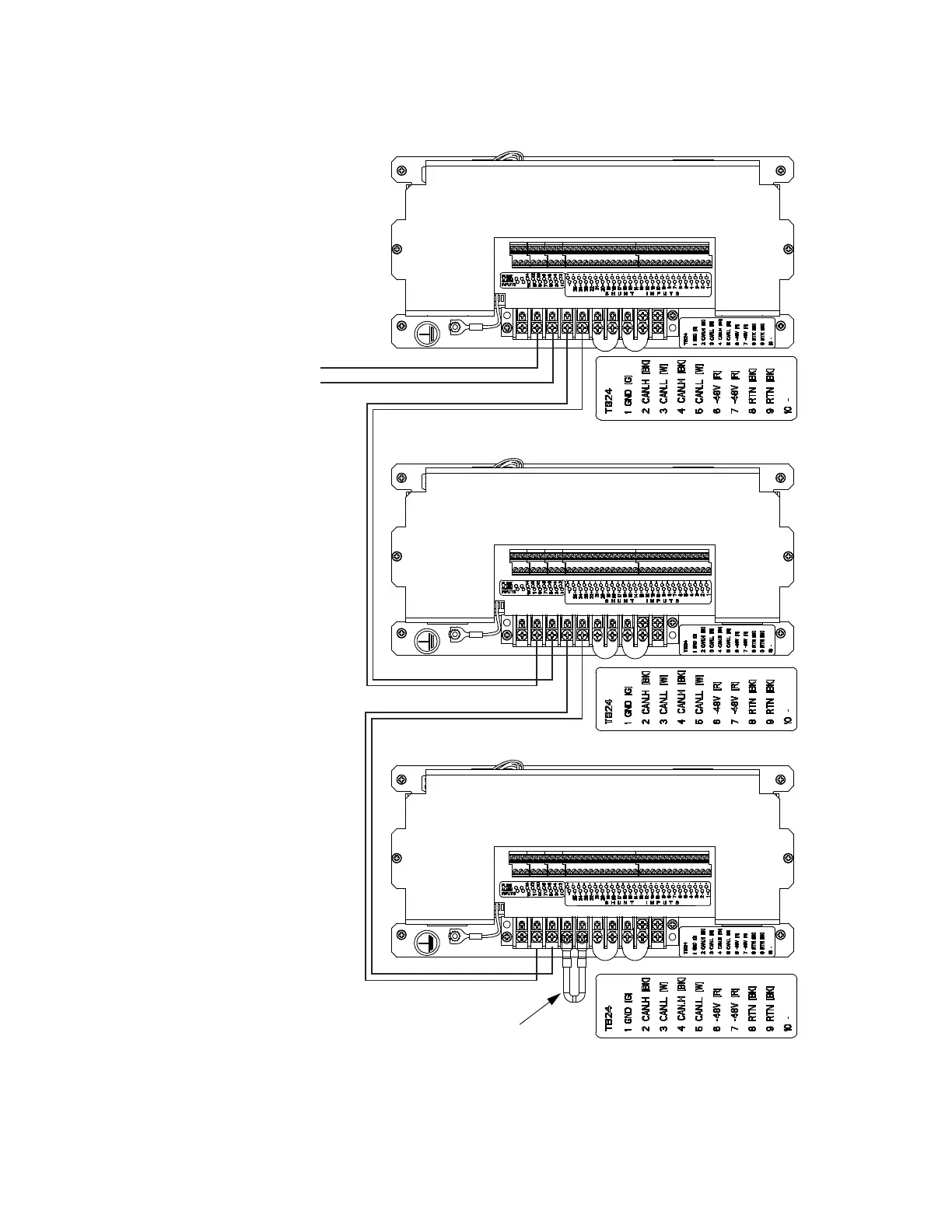
NetSure™ SM-DU+ Assembly Top View
Remove the termination
resistor from power system
CAN bus terminal block and
place it here (or use P/N
561768 termination resistor).
Cable P/N 562868 provided.
Twisted Wire Pair
CAN_H to CAN_H
CAN_L to CAN_L
Twisted Wire Pair
CAN_H to CAN_H
CAN_L to CAN_L

Other manuals for Vertiv NetSure 7100 Series

Questions and Answers:

Question and Answer IconNeed help?

Do you have a question about the Vertiv NetSure 7100 Series and is the answer not in the manual?

Vertiv NetSure 7100 Series Specifications

General IconGeneral
BrandVertiv
ModelNetSure 7100 Series
CategoryPower Supply
LanguageEnglish

Related product manuals