Vertiv™ NetSure™ Supervision Module for Distribution Unit Plus Installation and User Manual
4.7 NCU CAN Bus Connections
Refer to Figure 4.4.
Procedure (Connecting First Vertiv™ NetSure™ SM-DU+ Assembly to NCU)
1. Connect the NetSure™ SM-DU+ assembly into the NCU CAN Bus. Connect CAN_H to CAN_H. Connect CAN_L to CAN_L.
Refer to the system documentation for NCU CAN port description and location. Cable P/N 562868 provided. Refer to Table
4.1 for cable information. Refer to Figure 4.4 for an interconnect diagram.
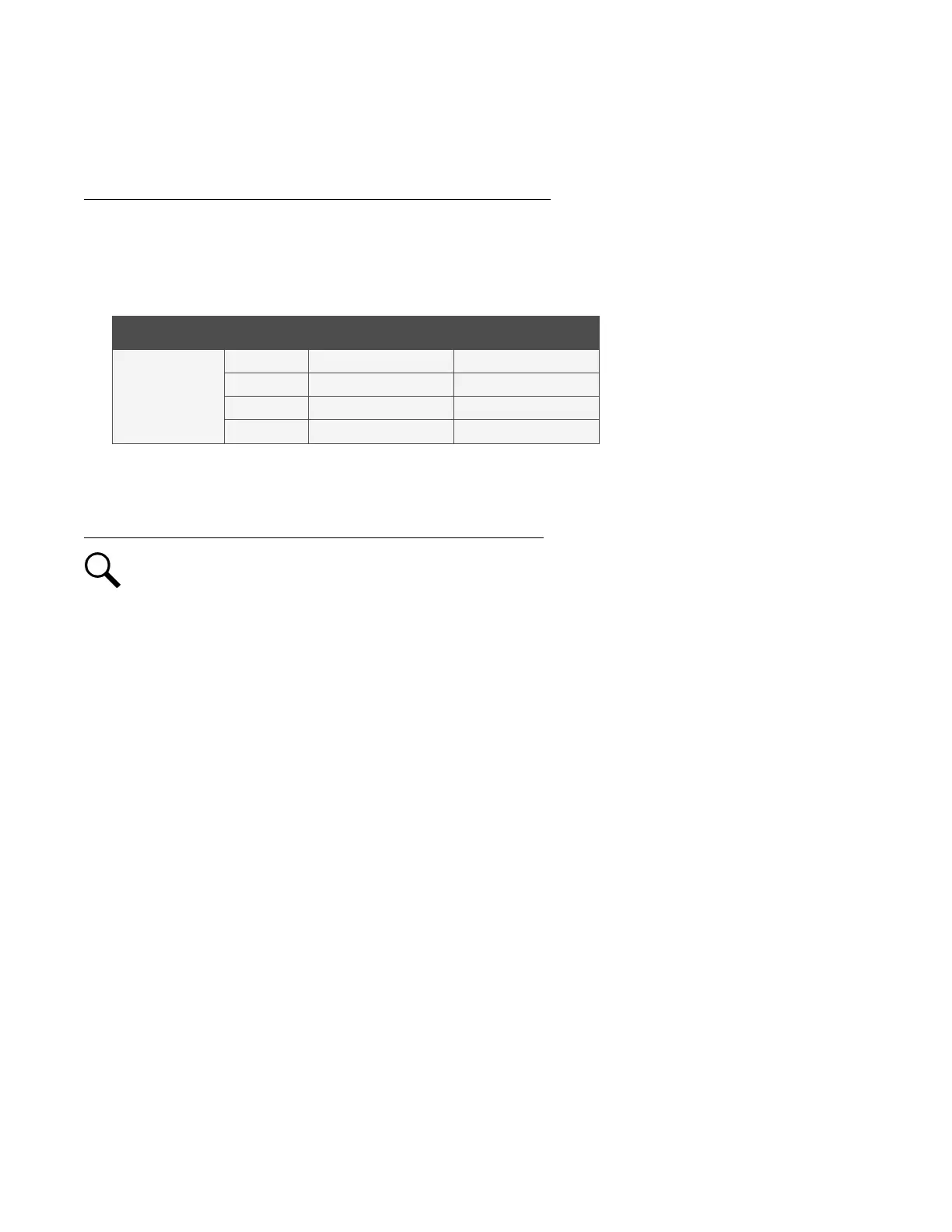
Table 4.1 CAN Bus Cable P/N 562868
Connector Pin No. Color Signal Symbol
RJ-45
1 W/O CAN_L
2 O CAN_H
4* BL CAN_H
5* W/BL CAN_L
* For use with NetSure 8200 and NetSure 802 retrofit kits.
Procedure (Connecting Multiple NetSure™ SM-DU+ Assemblies Together)
NOTE!
The NCU can communicate with up to eight (8) NetSure™ SM-DU+ assemblies. Set each NetSure™ SM-DU+
assembly to a unique address number.
1. To connect multiple NetSure™ SM-DU+ assemblies together, for all assemblies connect the CAN_H terminals together and
connect the CAN_L terminals together (CAN_H to CAN_H, CAN_L to CAN_L). See Figure 4.4 for an interconnect diagram.
2. Connect a termination resistor such as P/N 561768 to the last NetSure™ SM-DU+ assembly in the NCU CAN bus. Connect to
CAN_H and CAN_L terminals along with the CAN_H and CAN_L leads factory connected to the terminal block. See
Figure 4.4.

 Loading...


