Vertiv™ NetSure™ Supervision Module for Distribution Unit Plus Installation and User Manual
5 Operation
The Vertiv™ NetSure™ SM-DU+ assembly monitors load shunt inputs and fuse alarm inputs and reports this data to the NCU
controller.
5.1 Indicators
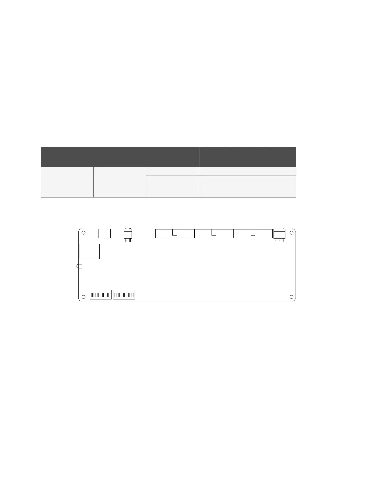
There is one (1) status and alarm indicator located on the NetSure™ SM-DU+ circuit card. The function of this indicator is as shown in
Table 5.1. Refer to Figure 5.1 for location.
Table 5.1 NetSure™ SM-DU+ Circuit Card Indicator
Indicator Normal State Fault State Fault Cause
Operation
(Green)
On
Off SM-DU+ is non-operational.
Flashing
A 1/3Hz flashing indicates the SM-DU+ is being
identified by the Controller.
A 1Hz flashing indicates a communication failure.
Figure 5.1 NetSure™ SM-DU+ Circuit Card Indicator Location
Green Indicator

 Loading...


