Vertiv™ NetSure™ Supervision Module for Distribution Unit Plus Installation and User Manual
4.6 Input Power Connections
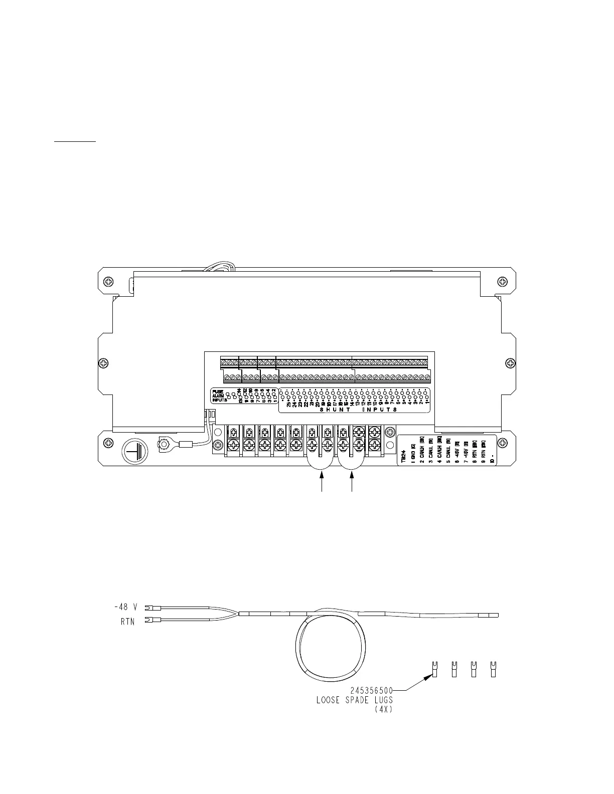
Input power must be supplied to each Vertiv™ NetSure™ SM-DU+ assembly installed in the system. A cable is factory provided for
this connection. The ungrounded input lead should be fused at 1-1/3 ampere. Refer to Figure 4.3 for input power connection location.
Procedure
1. Connect the spade lug end of cable P/N 557012 provided to the appropriate terminals located on the NetSure™ SM-DU+
assembly (see Figure 4.3.). Red to a -48V terminal, Black to a RTN terminal.
2. Route this cable to the input power source. Cut this cable to length and terminate it with the supplied spade lugs. Connect
Red to the -48V power source terminal. Connect Black to a RTN power source terminal.
Figure 4.3 NetSure™ SM-DU+ Assembly Input Power Connections
Screw: #6-32 Philslot
Recommended Lug: #6 Spade
Distance between Barriers: 0.30”
Torque: 9.0 in-lbs.
Use cable P/N 557012 to connect -48V and RTN
to the NetSure™ SM-DU+ Assembly.
-48V: Red Wire
RTN: Black Wire
-48V: Red Wire RTN: Black Wire
NetSure™ SM-DU+ Assembly Top View
P/N 557012 Cable Assembly (provided)

 Loading...


