Vertiv™ NetSure™ Supervision Module for Distribution Unit Plus Installation and User Manual
1 Introduction
1.1 Overview
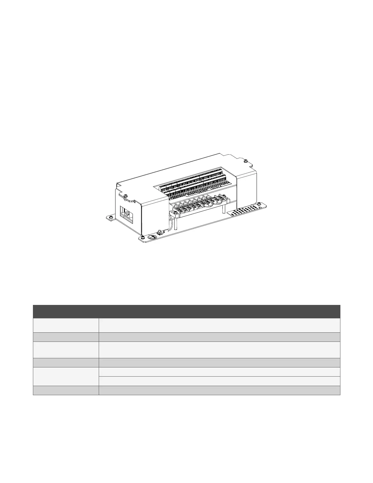
This assembly consists of a Vertiv™ NetSure™ SM-DU+ enclosed in a sheet metal housing. This assembly is used in applications
where the NetSure™ SM-DU+ is mounted external to a power system equipped with an NCU controller. The NetSure™ SM-DU+
assembly is used to connect load shunts and fuse alarm signals to the NCU controller. The NetSure™ SM-DU+ assembly provides
twenty-five (25) load shunt monitoring inputs and fourteen (14) fuse alarm monitoring inputs.
The NetSure™ SM-DU+ assembly connects into the NCU CAN bus. Up to eight (8) NetSure™ SM-DU+ assemblies can be connected
to an NCU. Refer to Figure 1.1 for an illustration of the NetSure™ SM-DU+ assembly.
Figure 1.1 NetSure™ SM-DU+ Assembly
1.2 Technical Specifications
See Table 1.1.
Table 1.1 Technical Specifications
Item Description
Operating Voltage
Nominal: -48 VDC.
Input Voltage Range: -19 VDC to -60 VDC.
Input Current <2 Amps
Operating
Temperature Range
Normal Operation Temperature Range: -10°C to +65°C.
Non Destructive Range: -40°C to +75°C.
Communication CAN Bus
Input Signals
Fourteen (14) Fuse Alarm (Bus- base of 0 VDC, >10 VDC alarm, <10 VDC normal).
Twenty-Five (25) Load Shunts (25 mV DC to 75 mV DC Shunt)
Dimensions See Figure 1.2.

 Loading...


