Vertiv™ NetSure™ Supervision Module for Distribution Unit Plus Installation and User Manual
4.4 Load Shunt Input Connections
The Vertiv™ NetSure™ SM-DU+ assembly provides connections for up to twenty-five (25) load shunt inputs.
See also “Switch Settings” on page 3.
Procedure
1. Connect up to twenty-five (25) load shunt inputs to the NetSure™ SM-DU+ assembly. Observe proper polarity. Refer to
Figure 4.2 and the label on the NetSure™ SM-DU+ assembly for connection point identification.
NOTE!
The shunt needs to be installed in the hot (-48V) bus. Connect the plus side of the shunt to the positive shunt input
on the NetSure™ SM-DU+ assembly. Connect the negative side of the shunt to the negative shunt input on the NetSure™
SM-DU+ assembly.
4.5 Fuse Alarm (FA) Input Connections
The NetSure™ SM-DU+ assembly provides connections for up to fourteen (14) fuse alarm (FA) inputs.
Procedure
1. Connect up to fourteen (14) fuse alarm (FA) inputs to the NetSure™ SM-DU+ assembly. Refer to Figure 4.2 and the label on
the NetSure™ SM-DU+ assembly for connection point identification.
- When a -48 VDC signal is applied to a fuse alarm input, the associated fuse alarm is inactive.
- When a -48 VDC signal is removed from a fuse alarm input, the associated fuse alarm is active.
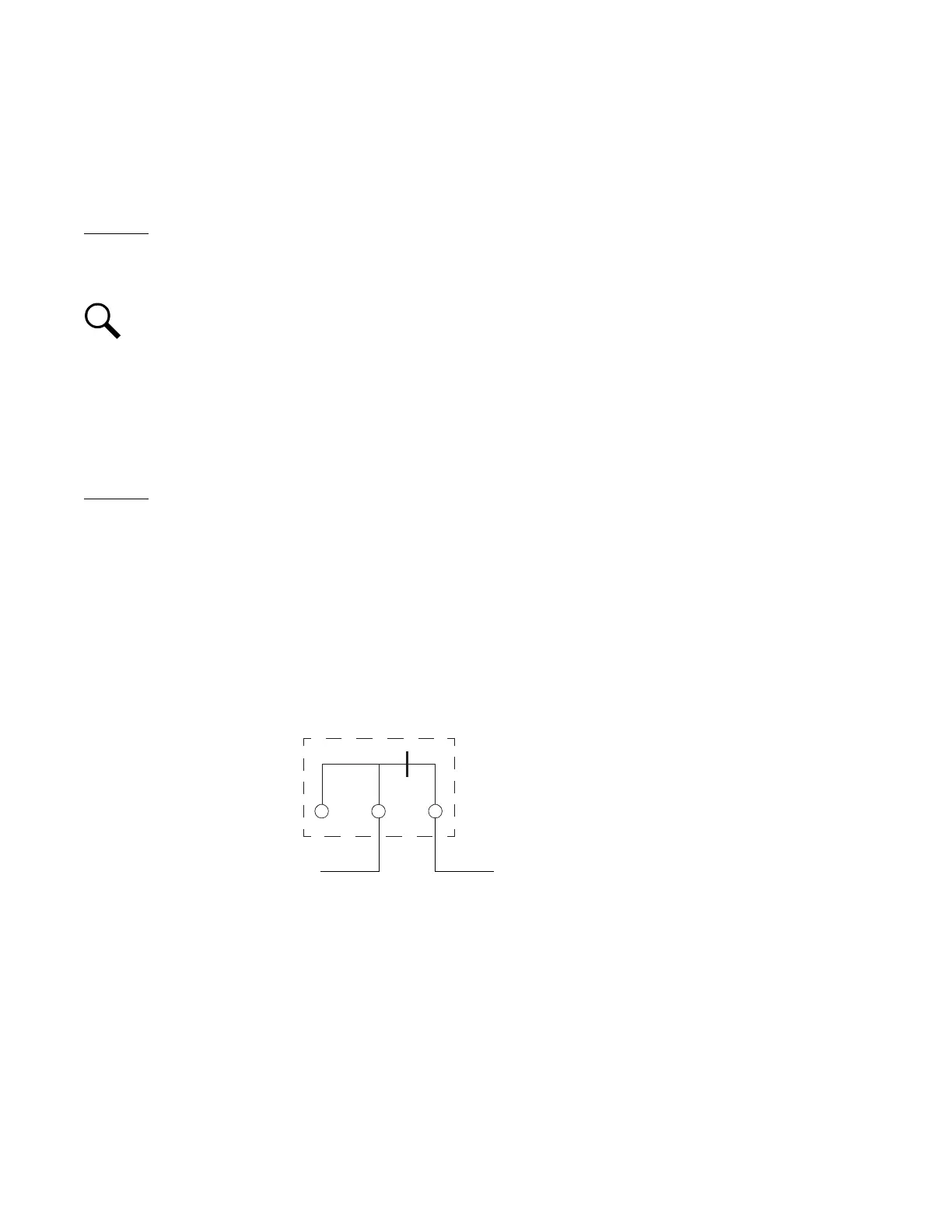
It is suggested to use an external fuse alarm Form-C relay contact. Connect the common (COM) terminal of the external fuse
alarm Form-C relay to a -48 VDC source and connect the normally closed (NC) terminal of the external fuse alarm Form-C
relay to one of the NetSure™ SM-DU+ FA inputs, as shown below.
2. Any of the fourteen (14) fuse alarms not being used needs to have their severity set to NA to indicate that this fuse alarm
input is not being used. Refer to the NCU manual for details.
Connect to NetSure™ SM-DU+ FA InputConnect to -48 VDC
External Fuse Alarm
Form-C Relay Contact
NO
COM
NC
X

 Loading...


