2022/04/05 13:27 11/26 SLICE-QTC Four-Channel Temperature Controller
Product Manuals - https://www.vescent.com/manuals/
dashed lines indicate the user-defined “lock range” (see figure 25). In figure 19, the lock range is set
to ±3 mK. If ∆T is outside of this range, the Error field background will change from green to yellow.
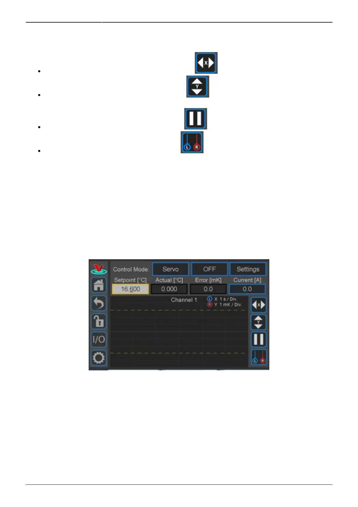
Change the speed of the rolling display: touch the button and select from 1 to 20 s/div.
Change the scale of the vertical axis: touch the button and select from 1 mK/div to 10
K/div.
Pause and restart the rolling screen: touch the button.
Turn on & off cursors on the graph: touch the button. It is possible to drag the cursors
across the display of ∆T to measure an oscillation period. This function will be helpful when
tuning the loop parameters to your plant.
Display of Transducer Current, Voltage, and Power
As shown in figure 19, the current being delivered to the transducer is displayed in the blue box on
the right margin labeled Current [A]. If you touch the blue box, the box will rotate through displaying
current through, voltage across, and power delivered to the transducer.
From this screen, you can also set the various parameters for how the loop will behave.
Fig. 19: Initial view of CH 1 Detail screen
Setting Control Modes
Touch the Settings button in the top right of the window. The sub-menu shown in figure 20 will
appear.