VESDA VLF-500 Product Guide VESDA by Xtralis
12 www.xtralis.com
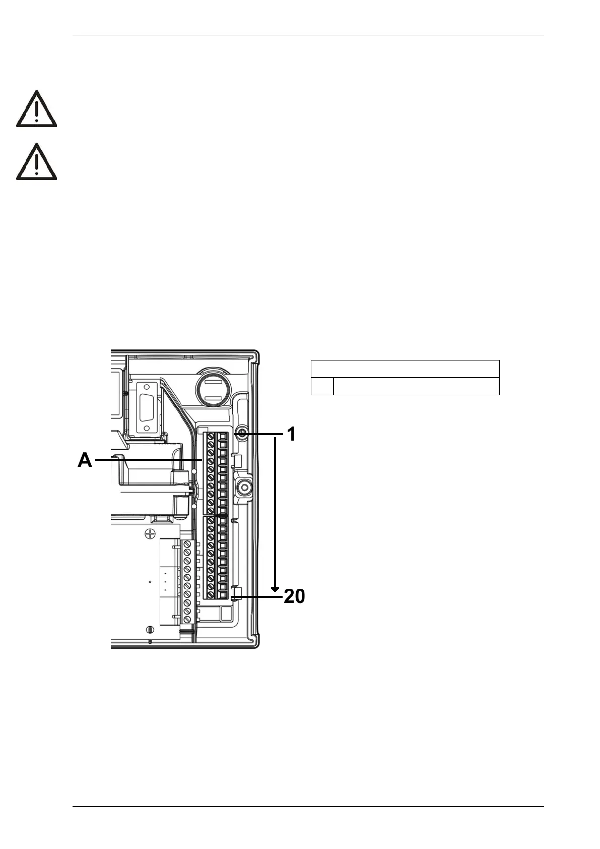
2.7 Wiring Connections
Caution: Electrostatic discharge precautions need to be taken prior to removing the front cover from the
detector otherwise damage may occur to the unit.
Attention : Il convient de prendre des précautions contre les décharges électrostatiques avant d'enlever le
capot avant du détecteur, sinon l'appareil risque d'être endommagé.
2.7.1 Detector cabling requirements
The screw type terminals located on the termination card within the VESDA VLF will accept wire sizes from
0.2 mm² to 2.5 mm² (30 – 12 AWG).
Refer to Codes and Standards Information for Air Sampling Smoke Detection on page iii for code-specific
requirements.
Refer to the VESDA System Design Manual for cabling details.
To reach the terminal block, open the field service access door, refer to Section 6.3 on page 31, and then
unscrew the front cover retaining screws. Lift off and swing down the front cover. The terminal block is located
on the right hand side of the detector.
Legend
A Terminal block, connectors 1-20
Figure 2-8: Terminal Block