VESDA VLF-500 Product Guide VESDA by Xtralis
14 www.xtralis.com
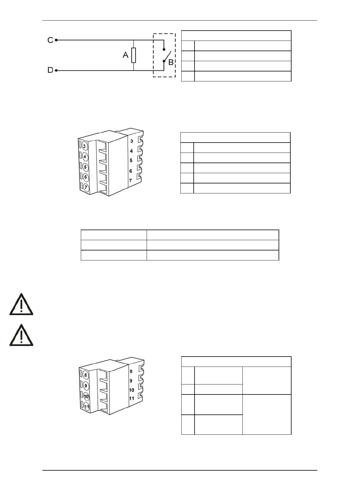
Legend
A End of Line Resistor (2.7k)
B External device (1 to N)
C GPI Pin 1
D GPI Pin 2
Figure 2-10: Triggering of GPI
2.7.3 Extra terminals (Terminals 3, 4, 5, 6 & 7)
Terminals reserved for future use.
Legend
3 Display Tx
4 Display Rx
5 Display Comm Gnd
6 Display Power -
7 Display Power +
Table 2-2: Terminal block display, spare power terminals
2.7.4 Power supply (Terminals 8, 9, 10 & 11)
Operating voltage: 24 VDC nominal (18 - 30 VDC)
Power consumption: 9.8 W nominal, 11.7 W in alarm
Current consumption: 410 mA nominal, 490 mA in alarm
It is recommended that the power supply be compliant with local codes and standards required by the regional
authority. For code-specific information, refer to Codes and Standards Information for Air Sampling Smoke
Detection on page iii.
Caution: Check the product termination wiring label during installation and subsequent maintenance
visits.
Attention : Vérifiez l'étiquette de câblage de terminaison à la pose et lors des visites de maintenance
ultérieures.
Legend
8 Power Return
0VDC
From power
supply unit
9 Power in 24VDC
10 Power Return
0VDC
To next detector
(if more than 1
detector per
Power Supply
Unit)
11 Power Out
24VDC
Figure 2-11: Terminal block display, power supply