DGT / DGT60 / DGTQ / DGTP
43
The active inputs are therefore IN 1 and, IN 2.
NOTES:
- The reading command of the inputs works also in the set-up environment
- No input is ascribed to bits from 2 to 15 bits and these are fixed at zero.
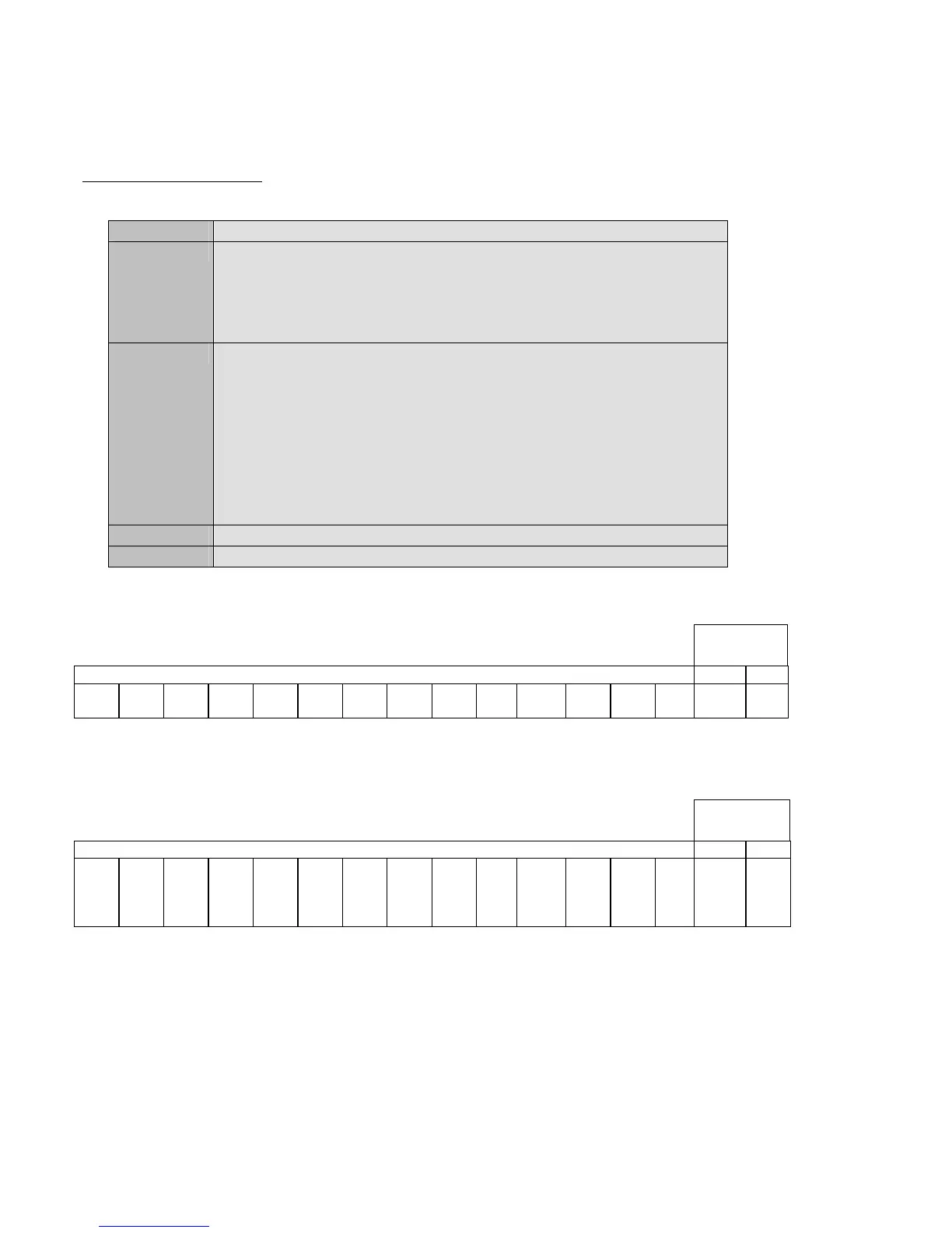
Output reading command:
Sintax
Format <ESC><II>OUTS<N><STX>
Parameters N = output number (expressed in hexadecimals):
- 0 to simultaneously read all the outputs.
- from 1 to 2 to identify the single input which one wants to read (from 1
to 6 with the DGTQ model).
Answer <ESC><II>OUTSNVVVV <STX>
previously
VVVV = outputs status:
- for the single output, V = 0000 means output not active, while V =
0001 active output, FFFF output reading error.
- for all the outputs (in other words N = 0), the returned value
corresponds to the hexadecimal codification of the status of the
outputs
Example <ESC>01OUTS0 <STX>
Result Reading of indicator’s outputs’ status (see the following explanation).
DGT and DGT60 models
A bit is ascribed to each input:
Board
outputs
Bit not managed RL 2 RL 1
Bit
15
Bit
14
Bit
13
Bit
12
Bit
11
Bit
10
Bit
9
Bit
8
Bit
7
Bit
6
Bit
5
Bit
4
Bit
3
Bit
2
Bit
1
Bit
0
Therefore if the OUTS00002 string is received, the hexadecimal value, converted into binary, indicates that the status
of the outputs is the following:
Board
outputs
Bit not managed RL2 RL 1
Bit
15
0
Bit
14
0
Bit
13
0
Bit
12
0
Bit
11
0
Bit
10
0
Bit
9
0
Bit
8
0
Bit
7
0
Bit
6
0
Bit
5
0
Bit
4
0
Bit
3
0
Bit
2
0
Bit
1
1
Bit
0
1
The active outputs are therefore RL 1 and, RL 2.
NOTES:
- The reading command of the outputs does not work in the set-up environment
- No output is ascribed to bits from 2 to 15 bits and these are fixed at zero.