the locking lever and positioning the table using a protractor or angle setter, then
retightening the locking lever.
2. Disk Table Adjustment
• Place an engineers square on the table
and slacken the locking levers slightly.
• Adjust the table so it is at right angles to
the Disc, using the square, then tighten
the locking levers.
• If necessary, adjust the pointer, adjacent
to the angle indicator beneath the table, (B
Fig.4), so that it registers zero.
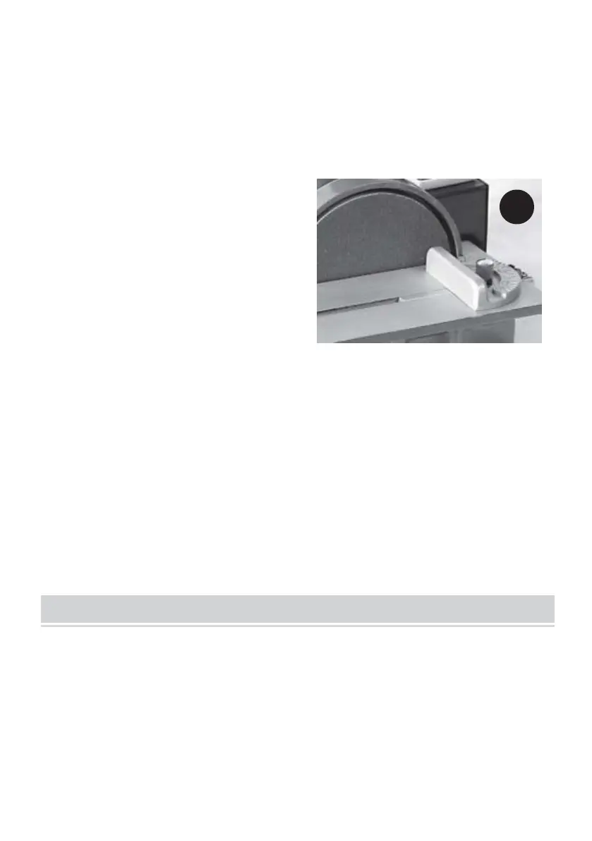
• Slacken the upper disc cover securing screws (A Fig.4) using the wrench
supplied, and adjust so that a gap of 2-3mm exists between the disc and table, and
the table is square. Tighten the securing screws.
• It is possible to set the table to any angle up to 45 degrees, simply by slackening
the locking levers and positioning the table using the angle indicator, then
retightening the locking levers. If the angle is critical, a protractor or angle setter
should be used.
• If required, slide the Quadrant into its groove in the table .
NOTE: The quadrant may be used to hold a workpiece at any desired angle for
sanding that angle with accuracy.
IMPORTANT!
Ensure that ALL components are secure, ALL correct adjustments have been
carried out, and ALL safety precautions have been observed BEFORE plugging
the machine into the mains supply, and switching ON.
1. Attach a vacuum cleaner or other dust extraction device to the relevant
extraction port (depending upon the medium to be used), and switch it ON.