3. Feet
The four feet may be very gently eased into the holes at the base of the machine.
Alternatively, the machine may be mounted on a workbench or a wooden base,
using the four holes in the base as mounting holes. In order to maintain complete
stability when in use, the wooden base should be secured to a workbench using
‘G’ clamps.
IMPORTANT ADJUSTMENTS - BEFORE USE
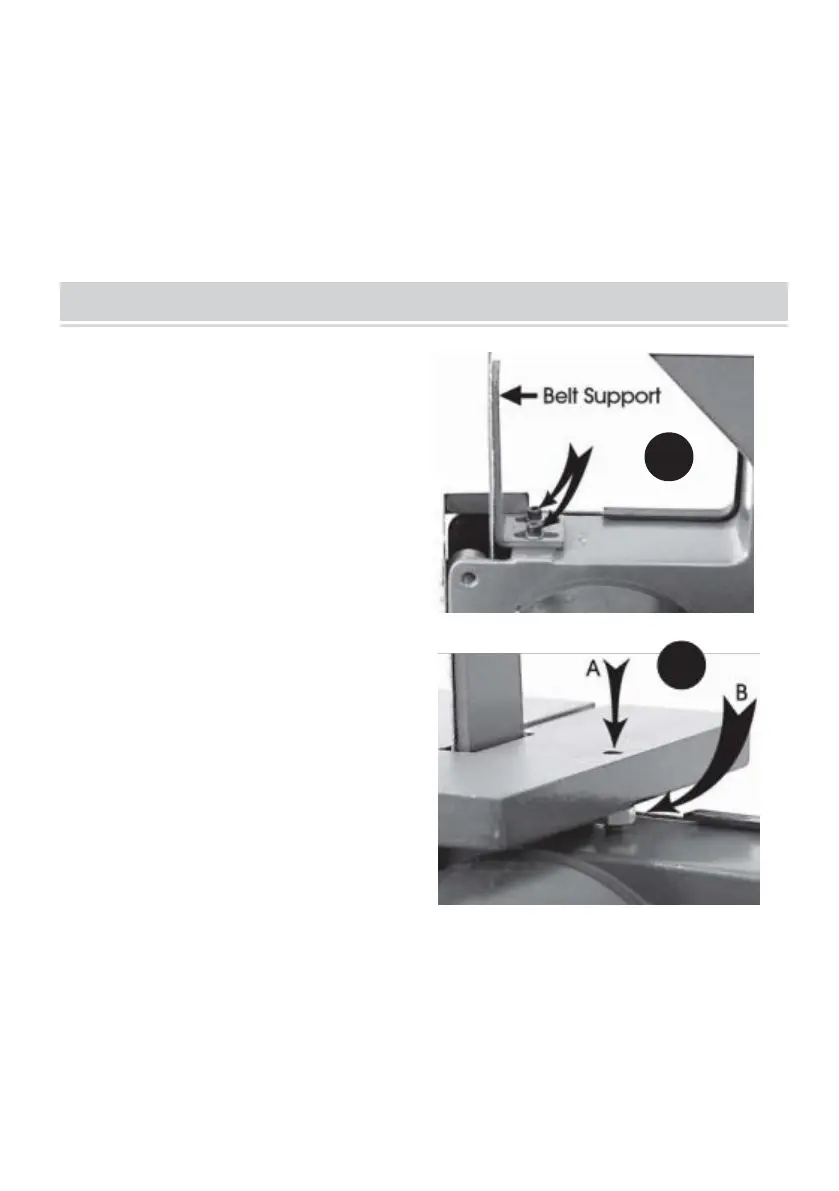
1. Belt Table Adjustment
• With the belt correctly tensioned (see
Maintenance), adjust the Belt Support
so that it is square and bears very lightly
on the back of the Sanding Belt. Ensure
the two hex socket head securing
screws (arrowed) are tight. A hex. socket
wrench is provided.
• Slacken the Table Locking Lever and
position the table so that a gap of 1.5 - 2
mm exists between the slot in the table
and the belt, then lightly secure the table
using the locking lever.
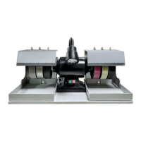
• Place an engineers square on the
table so that it butts up against the belt,
then unlock the adjuster by unscrewing
the lock nut at 7B. Screw the adjuster 7A,
clockwise or anticlockwise whilst bearing
down on the table at a point adjacent to screw 7A, until the square indicates that
the table is at right angles.
• Lock the adjuster, ensuring the nut is tight, then, maintaining pressure on the
table, finally secure the table using the locking lever. by turning anticlockwise.
•
Finally, check to ensure the gap between the table and belt is between 1.5 - 2 mm.
• It is possible to set the table to any angle up to 45 degrees, simply by slackening