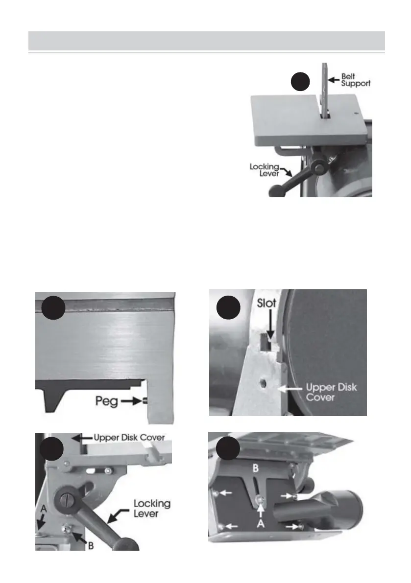
1. Belt Table
• Gently ease the table into place with the belt
support entering the slot in the table.
• Screw the Table Locking Lever into place,
ensuring a flat washer is used on the levers ’
threads noting that the locking lever has a LEFT
HAND thread, i.e. turn anticlockwise to tighten.
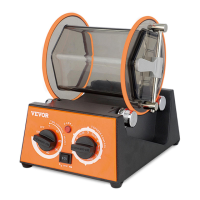
2. Disk Table
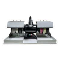
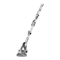
• Slide the table pegs (Fig 2) into the slots in the Upper Disk Cover (Fig . 3) to the
extent that the Locking Levers can be screwed in as shown in Fig . 4, ensuring flat
washers are used on the locking lever threads