15
OPERATION
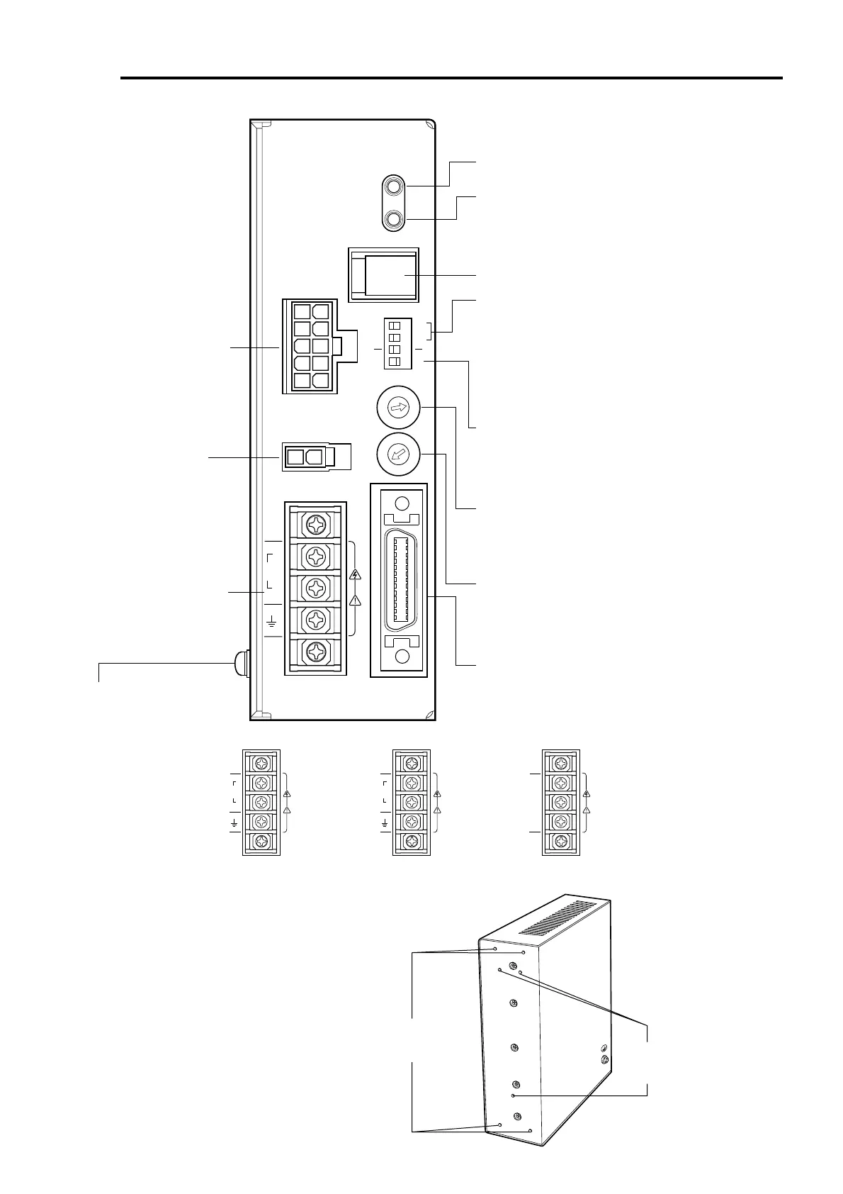
ALARM
CN1
CN2
CN3
MOTOR
CURRENT
L
100-
115V
N
~
CN4
I
O
/
V.FIL
1 2 3 4
0
1
2
3
4
5
6
7
8
9
A
B
C
D
E
F
0
1
2
3
4
5
6
7
8
9
A
B
C
D
E
F
1P
X1
1000
500
X10
2P
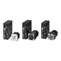
ASD24A-A
VEXTA
Resolution selection switches [P.43]
Use these two switches to select the motor resolution.
1000/500: Switches motor resolution between 1000 P/R
"0.36˚/pulse" or 500 P/R "0.72˚ //pulse."
×1/ ×10: Switches motor resolution between multipliers 1 and
10 of the value set by the 1000/500 switch.
The factory setting is "1000: 1000 P/R" and "×1: Multiplier 1."
Be sure to switch to "×1" when the resolution switching input
"CN4 Pin No. 31, 32: ×10" is used.
Pulse-input mode selection switch [P.44]
Allows for the selection of 2-pulse input mode or 1-pulse input
mode in accordance with the pulse-output mode in the
positioning controller.
The factory setting is "2P: 2-Pulse Input Mode."
Front side of driver
Not used (CN1)
Motor connector (CN2)
[P.31,32]
Connect the motor cable's
connector.
Regeneration unit
connector (CN3)
Control input/output connectors (CN4) [P.25,26,27,33,34,35]
Used to connect to the motor-positioning control and others.
Power supply terminal
[P.28,29,30]
Connect the power-supply
cable.
OPERATION (green)
Lit when the power is on.
ALARM (Red) [P.46]
This alarm blinks when a protective function is triggered and
the ALARM output turns "OFF."
Count the number of blinks to ascertain the cause of triggering
of the protective function.
Current setting switch [P.44]
Sets the motor's operating current.
If there is extra torque, the current may be set to a lower level
in order to suppress increases in motor temperature.
The factory setting is "F: Driver's maximum output-current value."
Speed-filter selection switch [P.45]
Sets the time constant for the filter that determines motor response.
A longer time constant will smooth out the motor's rotation but
render the setting time longer at motor standstill.
The factory setting is "6: 1.20 ms."
Protective earth terminal [P.33]
Used for grounding via a
grounding cable of AWG18
(0.75 mm
2
) or more.
Rear side of driver
Mounting holes for the driver
mounting brackets
(M3, four locations) [P.19]
Mounting holes for the DIN rail
mounting plate
(M3, three locations) [P.21]
•
Driver power-supply terminal
Single-phase 100-115 V
•
Driver power-supply terminal
Single-phase 200-230 V
•
Driver power-supply terminal
Three-phase 200-230 V
L1
L2
L3
L
100-
115V
N
~
L
200-
230V
N
~
Driver
 Loading...