3
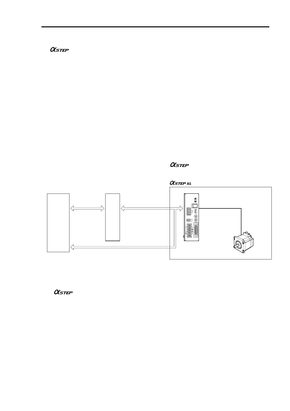
System configuration
Controllers with pulse-output functions are needed to operate the AS series.
• Be sure to purchase the extension cable (for use in the model with electromagnetic brake), which is sold separately,
when using the model with the electromagnetic brake. When the motor cable is directly connected to the driver, the
electromagnetic brake will not work. Use a 24 VDC power source for the electromagnetic brake.
• The AS series is available in three input-power sources: single-phase 100-115 V, single-phase 200-230 V
and three-phase 200-230 V.
Main features
• Low-speed operation at low vibration levels
The AS series achieves smooth, low-speed operation with extremely low vibration, thanks to its micro-stepping
drive, which enables stepping in very small angles.
• Built-in alarm function
Whenever a load greatly exceeding the motor rating is encountered, or when the motor’s output shaft is constrained
during operation, the driver outputs a warning alarm.
In a vertical-travel application, the electromagnetic brake may be triggered upon the detection of this alarm to prevent
a moving section or the work from falling.
• Preset speed filter
The filter time constant that determines motor response can be set in 16 increments.
• Preset operating current
The level of motor current during operation can be set between 6 and 100% (maximum) in 16 increments.
• Preset resolution
The motor resolution levels can be set in four increments: 0.72°/pulse, 0.36°/pulse, 0.072°/pulse and 0.036°/pulse.
Controller
(programmable controller
and others)
Control input
and output
Positioning controller
Pulse output and control
input/output
Shielded cable with
connectors (sold separately)
series
Driver
Motor
Extension cable (sold separately)
OPERATION
ALARM
CN1
CN2
CN3
MOTOR
CURRENT
L
100-
115V
N
~
CN4
I
O
/
V.FIL
1 2 3 4
0
1
2
3
4
5
6
7
8
9
A
B
C
D
E
F
0
1
2
3
4
5
6
7
8
9
A
B
C
D
E
F
1P
X1
1000
500
X10
2P
VEXTA
ASD24A-A
Control input and output
 Loading...