32
Note
• Applying a voltage over the
specification will increase the
temperature rise in the
electromagnetic brake and may
damage the motor.
Conversely, insufficient voltage
may prevent the brake from
releasing.
• Be sure to connect the varistor
(non-polarized) to protect the
switch contacts and prevent
noise.
• The lead wires for the
electromagnetic brake are
polarized. Connecting the lead
wires in reversed polarity will not
properly operate the
electromagnetic brake.
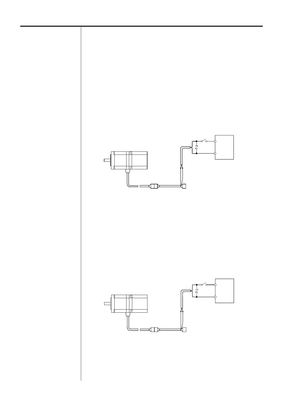
Using an electromagnetic-brake-type flexible cable (sold separately)
Model: CC01SARM2, CC02SARM2, CC03SARM2,
CC05SARM2, CC07SARM2, CC10SARM2
Use two (orange and gray) lead wires [60 mm (2.36 in.)] from the driver’s connector side.
1.Connect the orange lead wire to the +24 V terminal of the DC power supply.
2.Connect the gray lead wire to the GND terminal of the DC power supply.
3.Connect the varistor in parallel across the +24 V and GND terminals of the DC power supply.
The varistor is non-polarized.
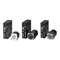
+24 V
GND
DC power supply for
electromagnetic brake
Varistor (provided)
GrayOrange/black
Electromagnetic-brake-type extension cable
(sold separately)
Gray
Orange/black
+24 V
GND
DC power supply for
electromagnetic brake
Varistor (provided)
Orange Gray
Electromagnetic-brake-type flexible cable
(sold separately)
Orange
Gray
Connecting power supply for the electromagnetic brake
Provide a DC power-supply cable of 24 VDC±5% at 0.3 A or more.
Use a shielded cable of AWG24 (0.2 mm
2
) or more in diameter to connect the electromagnetic
brake to the DC power supply, keeping the length as short as possible.
Using an electromagnetic-brake-type extension cable (sold separately)
Model: CC01AIPM, CC02AIPM, CC03AIPM, CC05AIPM, CC07AIPM, CC10AIPM,
CC15AIPM, CC20AIPM
Use two (orange/black and gray) lead wires [60 mm (2.36 in.)] from the driver’s connector side.
1. Connect the orange/black lead wire to the +24 V terminal of the DC power supply.
2. Connect the gray lead wire to the GND terminal of the DC power supply.
3. Connect the varistor in parallel across the +24 V and GND terminals of the DC power supply.
The varistor is non-polarized.
 Loading...