34
2. Attach the other connector cover and clamp both connector covers together with screws
and nuts.
Assembling the control input/output connector
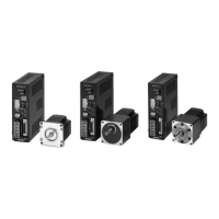
Solder the control input/output cable to the half-pitch connector (36 pins), then install the
connector cover over the half-pitch connector.
Soldering the cable to the half-pitch connector
Solder the input/output signal cable
(AWG28: 0.08 mm
2
or more) to the half-pitch connector
(36 pins).
For the pin assignments, refer to page 35.
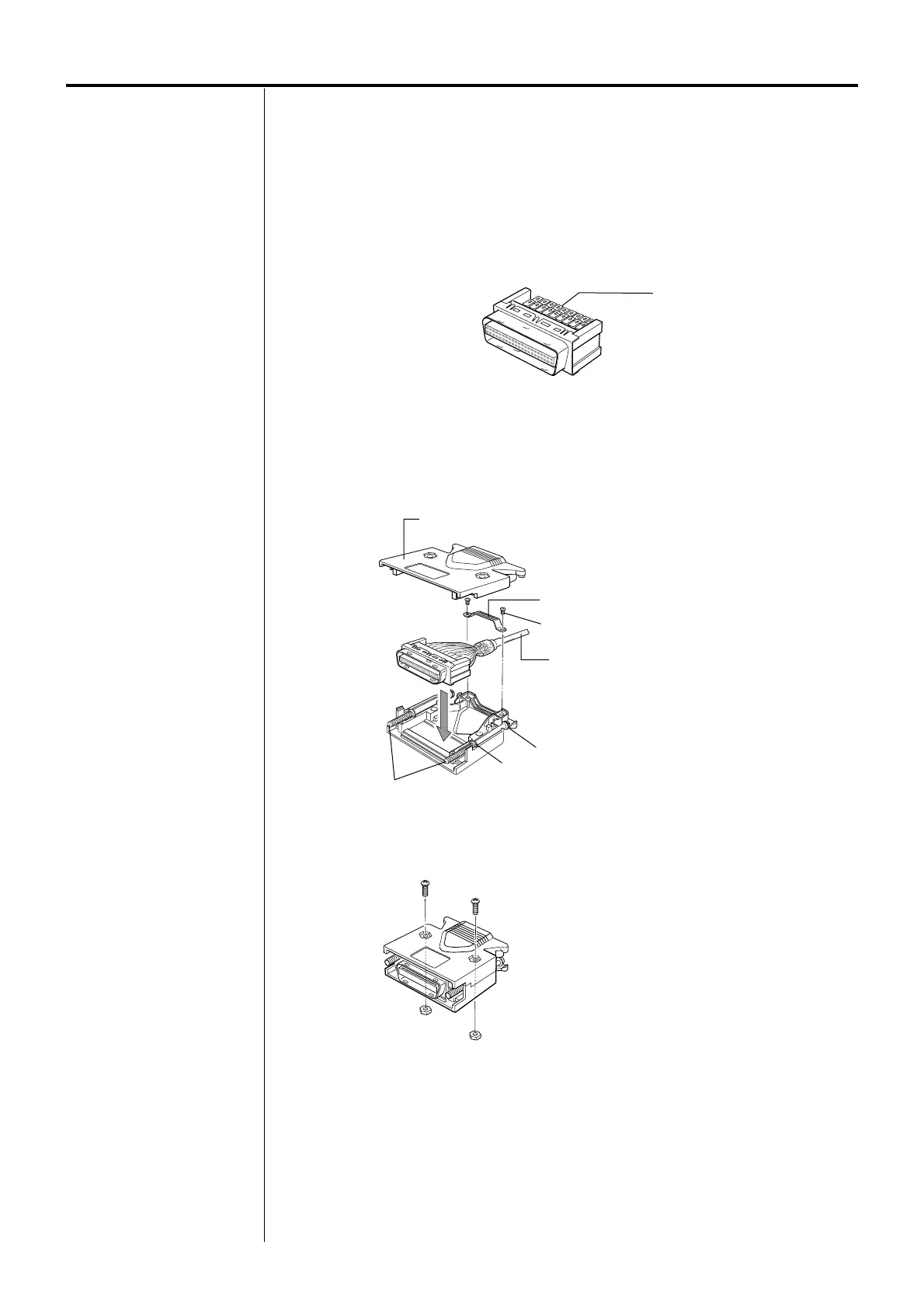
Assembling the half-pitch connector and the connector cover
1. Attach the supplied screws (two pieces) to the connector cover and insert the half-pitch
connector with the control input/output cable soldered to it. Adjust the cable clamp to its
correct position.
Half-pitch connector
Connector pin
Control input/output cable
Cable clamp
Screw
Connector cover
Half-pitch connector
Place the spring washer outside the connector cover.
Screw (M2)
Align the washer in the depression in the connector cover.
Clamp with screws (M2.5) and hexagonal nuts.
Tightening torque: 0.5 to 0.55
N·m (70.8 to 77.9 oz-in)
 Loading...