27
12. SettheaddresswiththeDNcommand.
Input: nDN=“x”[Ctrl-J]
The n represents the address assigned by the hardware switches in step
10.The“x”representstheaddressyouareassigningviathesoftware
method,whichcanbeanysingleASCIIcharacterfroma-z,A-Z,or0-9.
The address must be enclosed with quotes during the naming process.
13. Savetheaddress.
Input: xSAVE[Ctrl-J]
14. SetallthreeaddressswitchestoOFF.(Ifthey’renotsettoOFF,the
switches will override the software setting on power up.)
15. TypeControl-C[Ctrl-C]. (Or cycle the power by removing power, waiting
fortheLEDtogoout,thenreapplyingpower.)
Repeatsteps9-15foreachadditionalcontroller.
Notes about party communication
•Thereisnosign-onmessageinpartymode.
•Allcommunicationsmustbeterminatedwith[Ctrl-J]. The Enter key will
notwork.IfEnterisaccidentallypressed,theMicroLYNXwillnotcom-
plete the command until a [Ctrl-J] is sent.
•WhenanindividualMicroLYNXisinpartymode,itmonitorscommunica-
tions looking for its address. If the first character in a communication
doesnotmatchitsaddress,thatMicroLYNXstops“listening”untila
[Ctrl-J] is detected. All devices “pay attention” after a [Ctrl-J]. Therefore
if you accidentally type a wrong character and the unit you are trying
to communicate with seems to be ignoring you, send a [Ctrl-J] to make
everyMicroLYNXstartmonitoringagain.
•WhenusingRS-232tocommunicateinamultipleMicroLYNXsystem,the
unit that is physically connected to the RS-232 cable must be configured
asthehost(HOST=1)becauseithandlesthetranslationtoRS-485and
sends/receivesfortheotherunits.Therecanonlybeonehost;therefore
allotherunitsmustbesettoHOST=0.
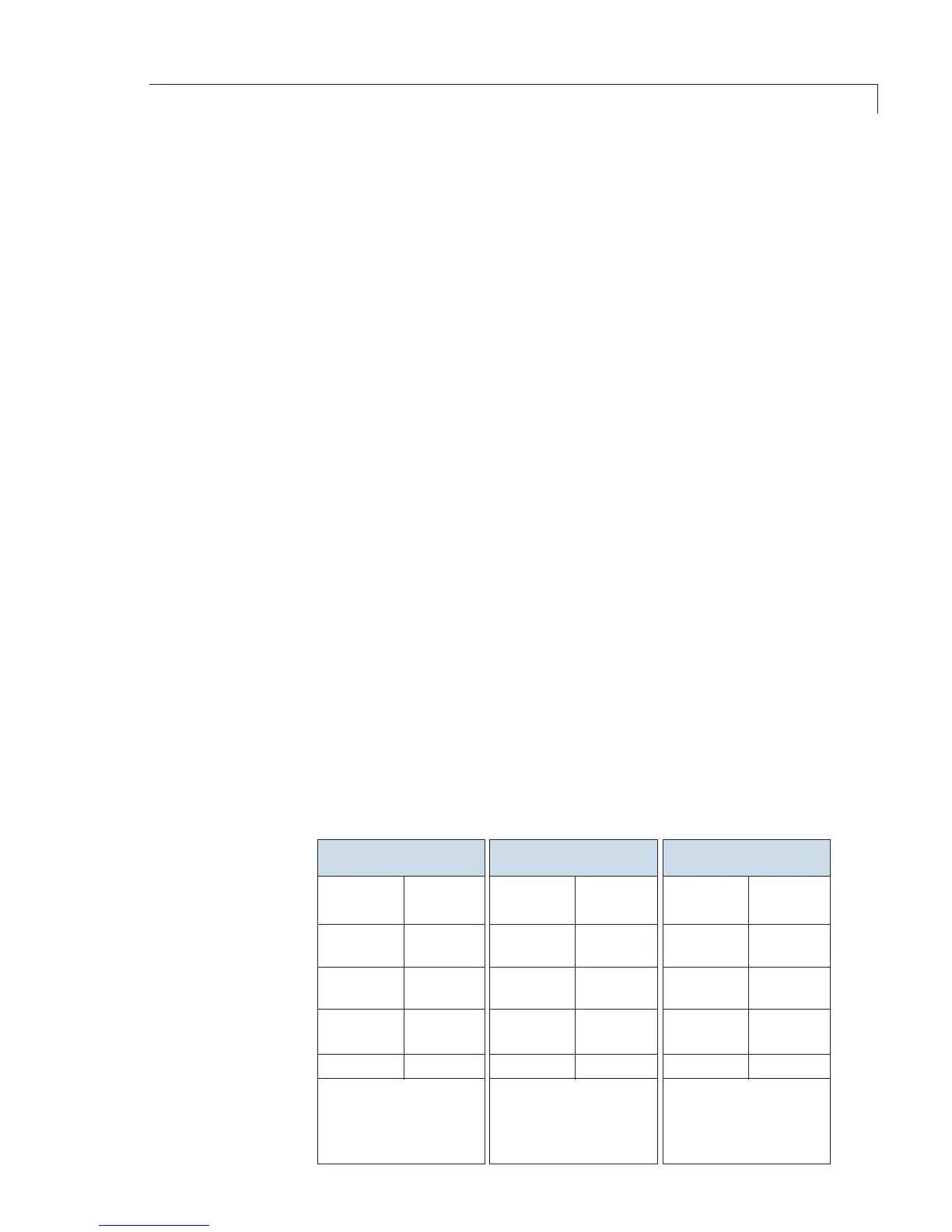
Setup for an M Series pump, a MicroLYNX controller, and a Valco valve
9 pin
D-shell
Signal
RS-232
7 pin
connector
Signal 3 pin Amp
connector
Signal
Pump Selection Valve
Setup for Multipump Operation