Screw
(Not in “set”
position)
Seal
Compression
Fitting
Drain
Hose
Body
Spring
Stem
Screw
(In “set”
position)
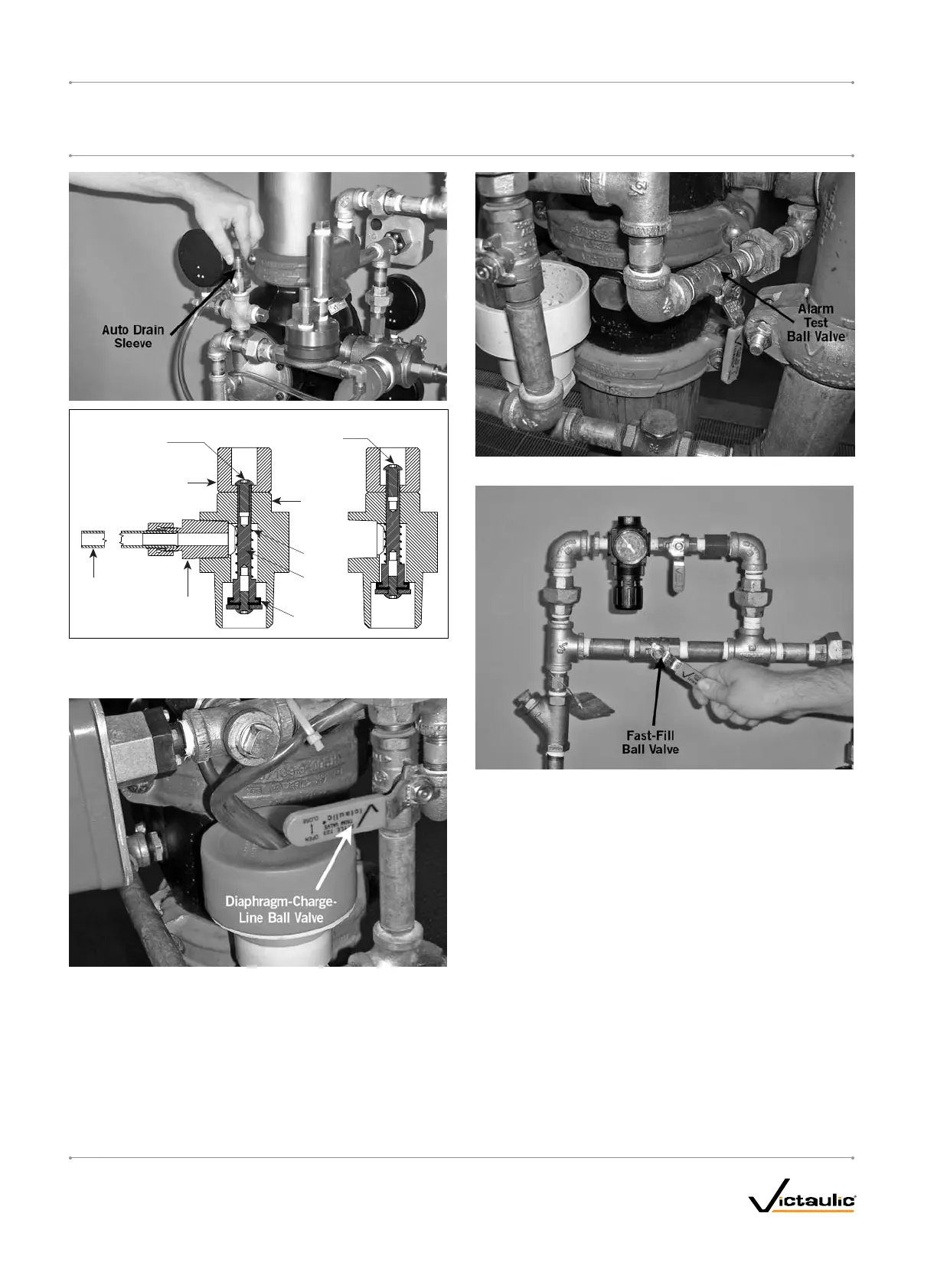
Sleeve
6. Confirm that water is flowing steadily from the Auto Drain. Pull up
on the Auto Drain Sleeve, and confirm that water is flowing through
the Series 776 Low-Pressure Actuator.
7. Close the diaphragm-charge-line ball valve.
8. Confirm that the alarm test ball valve is closed.
9. Charge the system with air by turning on the compressor or by
opening the fast-fill ball valve on the AMTA (fast-fill ball valve
is shown above). Charge the system to 13 psi/90 kPa/0.9 Bar
minimum. Refer to the “Air Supply Requirements” section.
9a. Confirm that the system is charging by observing the air
pressure gauge. If the gauge is not showing an increase in air
pressure, there is a leak or an opening in the line. Repair any
leaks or openings and restart the setup procedures.
10. Confirm that no water is being exhausted from the Auto Vent of
the Series 776 Low-Pressure Actuator. If water is being exhausted
from the Auto Vent, continue to run air through the system in
order to remove moisture from the upper chamber of the Series
776 Low-Pressure Actuator. If a Series 746-LPA Dry Accelerator is
installed, make sure the accelerator is not flooded.
I-768_14
FireLockNXT™DryValve
SERIES768
I-768
INSTALLATION,MAINTENANCE,ANDTESTINGMANUAL
www.victaulic.com
VICTAULIC IS A REGISTERED TRADEMARK OF VICTAULIC COMPANY. © 2007 VICTAULIC COMPANY. ALL RIGHTS RESERVED. PRINTED IN THE USA.
REV_D

 Loading...


