7. Align the holes of the diaphragm cover with the holes in the
diaphragm/valve body. Tighten all cap screws into the diaphragm
cover/valve body.
8. Re-attach the trim at the unions that were loosened in step 2.
Refer to the applicable trim drawing for details. MAKESURE
ALLUNIONSTHATWERELOOSENEDTOPERMITACCESS
TOTHEDIAPHRAGMCOVERARERE-TIGHTENEDBEFORE
ATTEMPTINGTOPLACETHESYSTEMBACKINSERVICE.
9. Place the system back in service by following the “Placing the
System in Service” section.
REPLACINGTHESTRAINERSCREENFORSERIES776LOW-
PRESSUREACTUATORS
1. Remove the system from service by following steps 1 – 10 of the
“Required Internal Inspection” section.
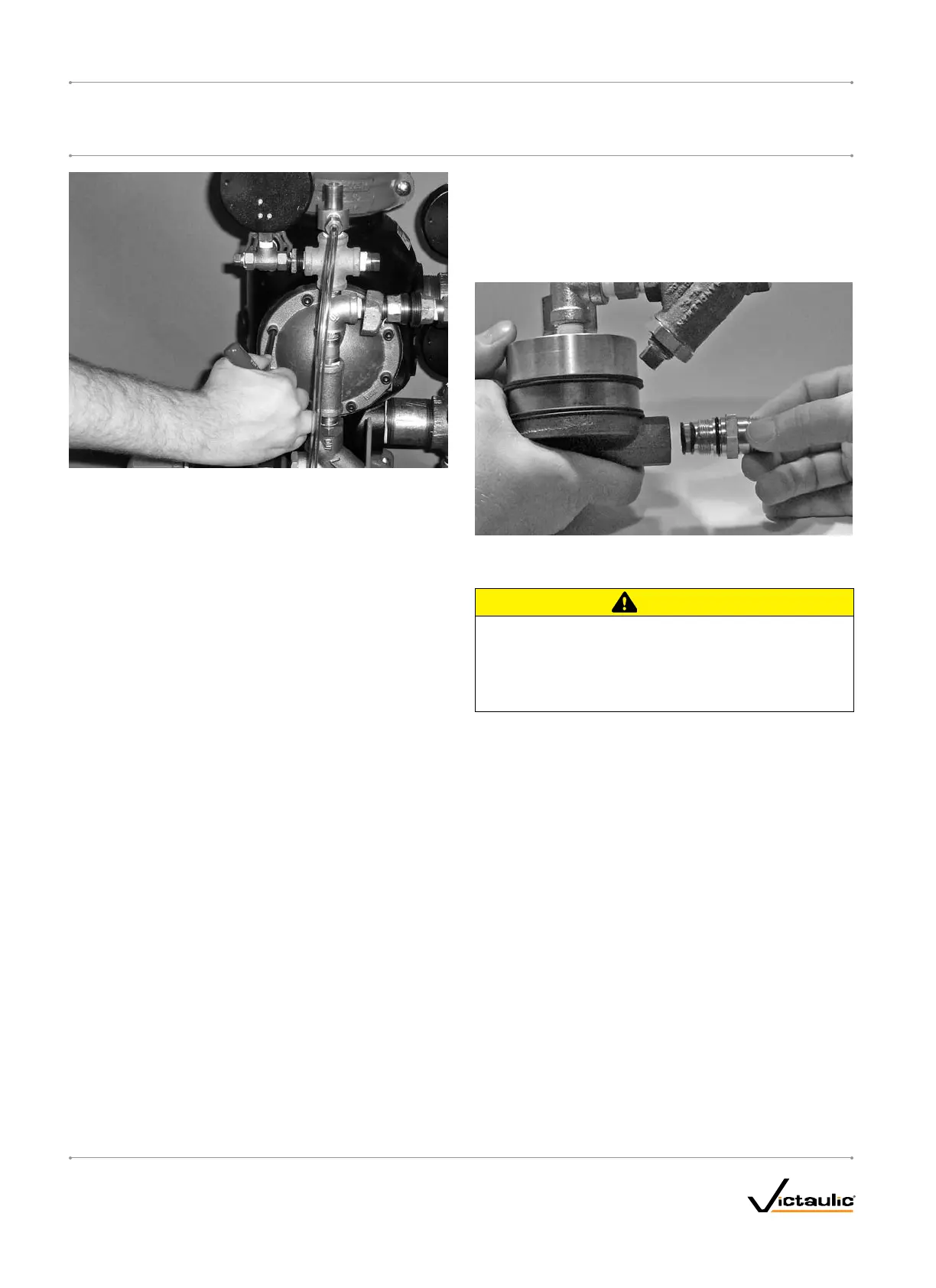
2. Remove the Series 776 Low-Pressure Actuator from the trim. Refer
to the applicable trim drawing for details.
3. Remove the strainer assembly from the Series 776 Low-Pressure
Actuator, as shown above. Discard the strainer screen only.
CAUTION
DONOTre-usestrainerscreens.Afterremoval,theold•
strainerscreenmustbereplacedwithanew,Victaulic-
suppliedscreen.
Failuretofollowthisinstructioncouldcauseimpropervalve
operation,resultinginpropertydamage.
4. Use only a new, Victaulic-supplied strainer screen. Insert the
strainer screen into the strainer assembly.
5. Install the strainer assembly into the Series 776 Low-Pressure
Actuator carefully. Avoid damage to the o-ring seals.
6. Re-install the Series 776 Low-Pressure Actuator into the trim.
Refer to the applicable trim drawing for details.
7. Place the system back in service by following the “Placing the
System in Service” section.
I-768_38
FireLockNXT™DryValve
SERIES768
I-768
INSTALLATION,MAINTENANCE,ANDTESTINGMANUAL
www.victaulic.com
VICTAULIC IS A REGISTERED TRADEMARK OF VICTAULIC COMPANY. © 2007 VICTAULIC COMPANY. ALL RIGHTS RESERVED. PRINTED IN THE USA.
REV_D

 Loading...


