TABLEOFCONTENTS
Hazard Identification ......................................1
Installer Safety Instructions .................................2
General ..............................................2
Maintenance and Testing .................................2
Introduction .............................................3
Trim Dimensions .........................................3
Exploded View Drawing – Trim Components ....................4
Exploded View Drawing – Trim Components ....................5
Exploded View Drawing – Internal Valve Components..............6
Section View Drawing and Description –
Series 776 Low-Pressure Actuator ..........................7
Section View Drawing and Description –
Series 746-LPA Dry Accelerator............................8
Air Supply Requirements ...................................9
Compressor Sizing ......................................9
Base or Riser-Mounted Air Compressors .....................9
Shop Air or Tank-Mounted Air Compressors...................9
Victaulic Series 757 Regulated Air Maintenance
Trim Assembly (AMTA) Option ...........................9
Victaulic Series 757P Air Maintenance Trim Assembly
(AMTA) with Pressure Switch Option .....................10
Compressor Requirements and Settings for
Series 768 FireLock NXT Dry Valves Installed with
Series 746-LPA Dry Accelerators ........................10
Settings for Air Supervisory Pressure Switches and
Alarm Pressure Switches ..............................10
Remote System Test Valve Requirements....................10
Important Installation Information ...........................11
Valve/Trim Installation ....................................11
Compression Fitting and Tube Installation ...................12
Hydrostatic Testing ......................................12
Placing the System in Service ..............................13
External Inspection ......................................18
Weekly Inspection .....................................18
Monthly Inspection ....................................18
Required Tests..........................................19
Main Drain Test .......................................19
Water Flow Alarm Test ..................................20
Water Level and Low Air Alarm Tests .......................22
Required Operational (Trip) Tests............................25
Partial Operational (Trip) Test.............................25
Full Operational (Trip) Test ...............................27
Required Internal Inspection ...............................29
Maintenance ...........................................32
Removing and Replacing the Clapper Seal...................32
Removing and Replacing the Clapper Assembly...............34
Installing the Cover Plate Gasket and Cover Plate..............36
Removing and Replacing the Diaphragm Assembly ............37
Replacing the Strainer Screen for Series 776
Low-Pressure Actuators ...............................38
Troubleshooting – Series 776 Low-Pressure Actuator .............39
Troubleshooting – Series 746-LPA Dry Accelerator...............39
Troubleshooting – System .................................39
HAZARD IDENTIFICATION
Definitions for identifying the various hazard levels are
provided below. When you see this symbol, be alert to the
possibility of personal injury. Carefully read and fully
u nderstand the message that follows.
WARNING
Theuseoftheword“WARNING”identifiesthepresence•
ofhazardsorunsafepracticesthatcouldresultindeathor
seriouspersonalinjuryifinstructions,includingrecommended
precautions,arenotfollowed.
CAUTION
Theuseoftheword“CAUTION”identifiespossiblehazardsor•
unsafepracticesthatcouldresultinpersonalinjuryandproduct
orpropertydamageifinstructions,includingrecommended
precautions,arenotfollowed.
NOTICE
Theuseoftheword“NOTICE”identifiesspecialinstructions•
thatareimportantbutnotrelatedtohazards.
I-768_1
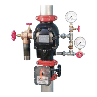
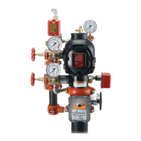
FireLockNXT™DryValve
SERIES768
I-768INSTALLATION,MAINTENANCE,ANDTESTINGMANUAL
www.victaulic.com
VICTAULIC IS A REGISTERED TRADEMARK OF VICTAULIC COMPANY. © 2007 VICTAULIC COMPANY. ALL RIGHTS RESERVED. PRINTED IN THE USA.
REV_D
 Loading...
