INSTALLINGTHECOVERPLATEGASKETANDCOVERPLATE
CAUTION
UseonlyVictaulic-suppliedreplacementparts.•
Failuretofollowthisinstructioncouldcauseimpropervalve
operation,resultinginpropertydamage.
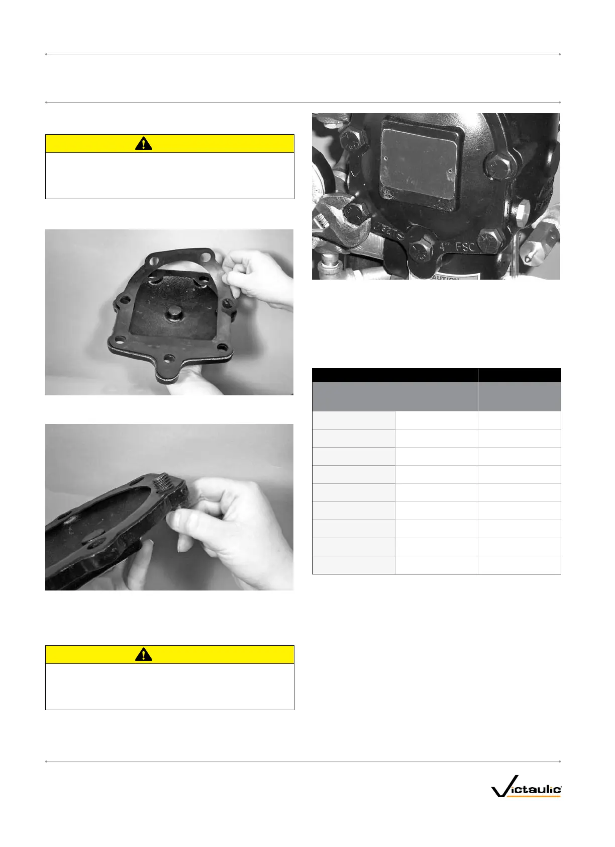
1. Verify that the cover plate gasket is in good condition. If the gasket
is torn or worn, replace it with a new, Victaulic-supplied gasket.
2. Align the holes of the cover plate gasket with the holes in the cover
plate.
3. Insert one cover plate bolt through the cover plate and cover plate
gasket to ease alignment. NOTE: For 1 ½-inch/48.3-mm and 2-
inch/60.3-mm valve sizes, a washer must be re-installed under the
head of each cover plate bolt.
CAUTION
DONOTover-tightenthecoverplatebolts.•
Failuretofollowthisinstructioncouldcausedamagetothe
coverplategasket,resultinginvalveleakage.
4. Align the cover plate/cover plate gasket to the valve. Make sure the
clapper spring’s arms are rotated to their installed position. Tighten
all cover plate bolts into the cover plate/valve body.
5. Torque all cover plate bolts in an even, crossing pattern. Refer
to the “Required Cover Plate Bolt Torques” table below for the
required torque values. DO NOT over-tighten the cover plate bolts.
REQUIREDCOVERPLATEBOLTTORQUES
Size Torque
Actual
OutsideDiameter
NominalSize
inches ft-lbs
inches
mm N•m
1 ½
1.900
48.3
30
41
2
2.375
60.3
30
41
2 ½
2.875
73.0
60
81
76.1mm
3.000
76.1
60
81
3
3.500
88.9
60
81
4
4.500
114 . 3
100
136
165.1 mm
6.500
165.1
115
156
6
6.625
168.3
115
156
8
8.625
219.1
100
136
6. Place the system back in service by following the “Placing the
System in Service” section.
I-768_36
FireLockNXT™DryValve
SERIES768
I-768
INSTALLATION,MAINTENANCE,ANDTESTINGMANUAL
www.victaulic.com
VICTAULIC IS A REGISTERED TRADEMARK OF VICTAULIC COMPANY. © 2007 VICTAULIC COMPANY. ALL RIGHTS RESERVED. PRINTED IN THE USA.
REV_D

 Loading...


